• Skip to main content
  • Skip to primary sidebar

Homemade Circuit Projects

Need circuit help? Post them in the comments! I've answered over 50,000!

Blog | Categories | About | Contact | Calculators-online
You are here: Home / Mini Projects / Footstep Activated LED Trouser Light Circuit

Footstep Activated LED Trouser Light Circuit

Last Updated on December 21, 2023 by Swagatam 1 Comment

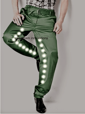
In this post I have explained how to transform your ordinary trousers into a chasing LED lit trousers which produces an shooting LED light chasing effect in response to your footstep movement or thumping.

Table of Contents
  • The Circuit Concept
  • Circuit Operation
  • Circuit Diagram

The Circuit Concept

The proposed foot step activated chasing LED trouser will enable you to decorate any piece of clothing with LEDs that will respond to your walking pattern or your footstep vibrations.

As long as you are motionless or not walking the LEDs will stay switched off, and as soon a foot step is detected, the LEDs will jump in a chasing or sequencing fashion to create a dazzling and fluctuating bar graph like effect.

The above feature is actually helpful in keeping the current consumption to the minimum so that the attached battery can last for a much longer duration of time compared to the other forms of LED trousers where the LEDs are always ON wasting precious battery power.

Moreover the idea generates an eye-catching running light effect with every step you take.

Circuit Operation

The circuit is actually a simple vibration sensor which relies on the vibrations picked up by an attached mic.

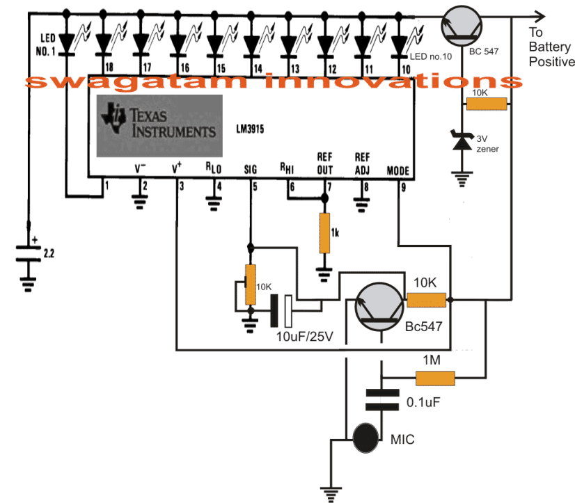
The sensing circuit is configured around the IC LM3915 which is a dot/bar LED driver chip, it's primary function is to convert minute voltage variations into correspondingly fluctuating output in the form of sequencing LED graph.

In the shown LED trouser chasing light circuit, when a vibration is detected (foot steps), the mic detects it and converts it into minute electrical pulses.

Precisely with every vibration impulse the mic momentarily produces short across it terminals, this results in momentary grounding of the base of the NPN transistor through the 0.1uF capacitor.

This in turn causes the base drive via the 1M resistor to become zero switching of the transistor momentarily.

This results in a full supply potential being allowed to pin#5 of the IC.

As per the specifications of the IC this causes the output of the IC to shoot and illuminate all the LEDs from LED#1 to LED#10 in a rapid sequencing pattern.

As soon as the foot step is paused the transistor is again switched ON shutting off all the LEDs in a blink.

The above action keeps on repeating as long the individual keeps walking creating a random shooting LED bar effect on the trousers.

The LEDs used should be high bright type preferably in blue/white/red colors or as per individual preferences.

The entire circuit could be powered by a single 9V PP3 battery, which should last for a long time unless you are running around non-sop with the LED trousers on, all night long.

Two such modules can be installed on the side stitch of the trouser legs, the mics should be place at the bottom of the trouser, preferably tied up with the heel side of the shoe, this should be done by terminating the mic through a few inches of flexible wires.

The shown 10k preset is for adjusting the sensitivity of the circuit so that the LEDs don't respond to external sounds such as loud music, vehicle horns etc.

Circuit Diagram

Footstep Activated LED Trouser Light Circuit

You'll also like:

  • 1.  12V LED String Light Flasher Circuit for Christmas Decoration
  • 2.  6 Best Ultrasonic Circuit Projects for Hobbyists and Engineers
  • 3.  LM10 Op Amp Application Circuits – Works with 1.1 V
  • 4.  Visitor Counter Circuit Using IC 555 and IC 4026
  • 5.  5 Interesting Flip Flop Circuits – Load ON/OFF with Push-Button
  • 6.  Circuit Projects for Beginners and School Students

Filed Under: Mini Projects Tagged With: Activated, Footstep, LED, Light, Trouser

About Swagatam

I am an electronics engineer and doing practical hands-on work from more than 15 years now. Building real circuits, testing them and also making PCB layouts by myself. I really love doing all these things like inventing something new, designing electronics and also helping other people like hobby guys who want to make their own cool circuits at home.

And that is the main reason why I started this website homemade-circuits.com, to share different types of circuit ideas..

If you are having any kind of doubt or question related to circuits then just write down your question in the comment box below, I am like always checking, so I guarantee I will reply you for sure!

Previous Post: « 3.7 V Li-Ion Battery Charger Circuit with Automatic Cut-off
Next Post: Automatic Generator Choke Actuator Circuit »

Reader Interactions

Comments

  1. Swagatam says

    December 14, 2013 at 6:04 am

    thanks mate:)

    Reply

Need Help? Please Leave a Comment! We value your input—Kindly keep it relevant to the above topic! Cancel reply

Your email address will not be published. Required fields are marked *

Primary Sidebar

circuit simulator image

Subscribe to get New Circuits in your Email

Categories

  • Arduino Projects (89)
  • Audio and Amplifier Projects (132)
  • Automation Projects (17)
  • Automobile Electronics (101)
  • Battery Charger Circuits (83)
  • Datasheets and Components (106)
  • Electronics Theory (143)
  • Free Energy (37)
  • Games and Sports Projects (11)
  • Grid and 3-Phase (19)
  • Health related Projects (25)
  • Home Electrical Circuits (12)
  • Indicator Circuits (14)
  • Inverter Circuits (88)
  • Lamps and Lights (142)
  • Meters and Testers (69)
  • Mini Projects (46)
  • Motor Controller (64)
  • Oscillator Circuits (28)
  • Pets and Pests (15)
  • Power Supply Circuits (108)
  • Remote Control Circuits (50)
  • Security and Alarm (64)
  • Sensors and Detectors (102)
  • Solar Controller Circuits (59)
  • Temperature Controllers (42)
  • Timer and Delay Relay (49)
  • Transmitter Circuits (29)
  • Voltage Control and Protection (40)
  • Water Controller (36)

Other Links

  • Privacy Policy
  • Cookie Policy
  • Disclaimer
  • Copyright
  • Videos
  • Sitemap

People also Search

555 Circuits | 741 Circuits | LM324 Circuits | LM338 Circuits | 4017 Circuits | Ultrasonic Projects | SMPS Projects | Christmas Projects | MOSFETs | Radio Circuits | Laser Circuits | PIR Projects |

Social Profiles

  • Twitter
  • YouTube
  • Instagram
  • Pinterest
  • My Facebook-Page
  • Quora
  • Stack Exchange
  • Linkedin
  • Recent Comments

    • Swagatam on How to Make Dog Barking Preventer Circuit using High Frequency Deterrence
    • Swagatam on How to Make Dog Barking Preventer Circuit using High Frequency Deterrence
    • Swagatam on Letter Box Open Indicator Circuit
    • Jim Meechan on How to Make Dog Barking Preventer Circuit using High Frequency Deterrence
    • Swagatam on Generator/Alternator AC Voltage Booster Circuit

    © 2025 · Swagatam Innovations