• Skip to main content
  • Skip to primary sidebar

Homemade Circuit Projects

Need circuit help? Post them in the comments! I've answered over 50,000!

Blog | Categories | About | Contact | Calculators-online
You are here: Home / Lamps and Lights / 1 watt LED Lamp Circuit Diagram using SMD LEDs

1 watt LED Lamp Circuit Diagram using SMD LEDs

Last Updated on January 17, 2025 by Swagatam 21 Comments

The post comprehensively discusses the construction procedure of a 1 watt LED lamp using SMD LEDs such as 3528 smd LEDs or 2214 SMD LEDs. I have explained the details.

Table of Contents
  • 1 Watt LED vs 3528 smd LEDs or 2214 SMD LEDs
  • Making a 1 watt LED using 3528 smd LEDs or 2214 SMD LEDs
  • Advantages using SMD LEDs
  • Disadvantages of SMD LEDs
  • Circuit Diagram

1 Watt LED vs 3528 smd LEDs or 2214 SMD LEDs

Today 1 watt LEDs are very popular and these are utilized in most LED lamp applications. Although these are extremely efficient in terms of light intensity levels and current consumption, these high watt LEDs require a formidable heatsink in order to keep them functioning correctly and optimally.

Without a heatsink, 1 watt LEDs can become completely useless as it would mean an immediate damage to the devices due to over heating and thermal runaway.

Moreover these LEDs require special aluminum base PCBs for the assembly, which in turn requires an external aluminum heatsink for added cooling.

All these compulsions make these LED modules fairly difficult to assemble and apply for hobbyists or any interested new electronic enthusiast.

However with the advent of many smaller SMD LED variants which range right from 20mA to 60mA, making 1 watt LEd equivalents with matching illumination and reliability is now a child's play, and since these smaller variants do not require heatsink for functioning makes them extremely desirable and feasible for the many newcomers in the field who may be avidly intrigued and interested to play with, and make their own LED light projects for their homes, and boast the same among their friends.

Making a 1 watt LED using 3528 smd LEDs or 2214 SMD LEDs

A 1 watt LED equivalent lamp can be quite easily made by incorporating a many 20mA or 50mA smaller LEDs and configuring these together with a suitable supply voltage.

In fact any high watt equivalent LED can be made by using these smaller low current LEDs as desired, therefore it's possible to make a 3 watt, or a 5 watt or even higher rated LED using the smaller counterparts such as the 3528 LEDs or the 2214 LEDs.

The advantage of using smaller LEDs for generating an equivalent illumination comparable to the 1 watt, 3 watt or 5 watt can be summarized as given below:

Advantages using SMD LEDs

Low current LEDs can be operated without the need of a heatsink, and over any ordinary PCB. The use of special, expensive aluminum base PCBs can thus be avoided with these LEDs.

Low current LEDs become compatible with transformerless capacitive power supply units, and therefore SMPS operation can be eliminated.

With a capacitive power supply in use, the need of a current control becomes immaterial because the input capacitor itself acts like an effective current controller and alone is able to restrict current to the calculated levels.

A high watt LED made by using low amp LED may have the capability of producing more illumination compared to a single identically rated high watt LED.

Due to the above comforts, such high watt equivalents can be easily built even by the noobs or people who are relatively new in the field of electronics.

Disadvantages of SMD LEDs

The only disadvantage is the involved size of such modules which could be slightly bigger area wise, and also the assembly could be slightly time consuming.

The following diagram shows an example 1 watt LED lamp circuit made by using 16nos of 2214 (20mA) SMD LEDs and a suitably rated transformerless power supply.

Circuit Diagram

Warning: the following circuit is not isolated from the AC mains, and prone to electric shocks. Therefore make sure that you are extremely careful while handling this circuit in an uncovered and powered condition.

1 watt LED Lamp Circuit Diagram using SMD LEDs

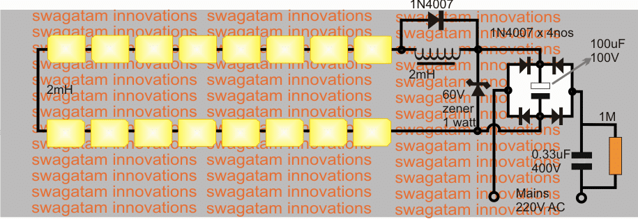
All the 20mA LEDs can be seen connected in series with a compact transformerless power supply.

A 20mH inductor can also be seen, this is included to arrest the initial switch ON surge, the zener diode provides an extra protection from any possible voltage fluctuations.

One may also include an NTC thermistor at the input for providing even greater protection to the LEDs from surge currents.

You'll also like:

  • 1.  How to Connect Car LED Downlight
  • 2.  Make this LED Driver Circuit for Backlighting Small LCD Screens
  • 3.  Arduino RGB Flowing Sequential Light Circuit
  • 4.  AC Light Dimmer Circuit
  • 5.  Single Ended nOOds, 300mm long Flexible LED Filament, Warm White 3V
  • 6.  Make this Plasma Ball Circuit

About Swagatam

I am an electronics engineer with over 15 years of hands-on experience. I am passionate about inventing, designing electronic circuits and PCBs, and helping hobbyists bring their projects to life. That is why I founded homemade-circuits.com, a website where I share innovative circuit ideas and tutorials. Have a circuit related question? Leave a comment.... I guarantee a reply!

Previous Post: « Simple Musical Door Bell Circuit
Next Post: Make this Gravity LED Lamp Circuit »

Reader Interactions

Comments

  1. Padmanabha J Revankar says

    November 13, 2021 at 7:11 am

    Sir thanks for your posts. I am a hobbyist and I want to connect 10 w smd leds for display purpose where Lithium batteries and 12w Solar panel used. Should run 8am to 10pm continously. Can I have the circuit pls

    Reply
    • Swagatam says

      November 13, 2021 at 1:25 pm

      Hello Padmanabha, can you provide the current and voltage specifications of the LEDs and the battery? And is the 10pm timing a fixed limit or an approximate limit?

      Reply
  2. Marc says

    December 15, 2020 at 12:28 am

    what is the maximum LED i can use on this circuit.
    Thanks!!

    thank you for sharing
    your knowledge????

    Reply
    • Swagatam says

      December 15, 2020 at 10:26 am

      You can get the number by dividing the zener voltage by the FWD voltage rating of the LED

      Reply
  3. Marc says

    December 12, 2020 at 8:55 pm

    This circuit is only for 220V.
    Is it possible to adapt this circuit for 120V (Canada)
    Thanks!!

    Reply
    • Swagatam says

      December 13, 2020 at 11:23 am

      It can be used with any voltage above 60 V, upto 310V, so you can surely use it for your 120V also.

      Reply
  4. Abdul Basit Momin says

    October 21, 2019 at 11:10 pm

    Hello sir wanted to known about Dob Pcb bulb how to make DOB 3592 bulb safe …….because if we put it on 230v ……….the bulb. In 2 to 3 days get blast

    Reply
    • Swagatam says

      October 22, 2019 at 9:47 am

      Hello Abdul, what is the input specifications of the module?

      Reply
      • Abdul Basit Momin says

        October 23, 2019 at 10:51 am

        Driver on Board Solution
        CYT IC used
        High Quality Led
        High quality Board
        Different Colours
        3W to 15W

        Reply
        • Swagatam says

          October 23, 2019 at 2:16 pm

          Does it have current control and voltage control?

          Reply
          • Abdul Basit Momin says

            October 24, 2019 at 12:13 pm

            No

            Reply
            • Swagatam says

              October 24, 2019 at 12:23 pm

              Add 60 watt or a 100 watt incandescent bulb in series with the input 220V, this will definitely protect your bulb forever.

              Reply
  5. Rajib Paul says

    November 22, 2016 at 12:09 pm

    Bright Led Light Circuit 2 or 5 watt from 230v Ac.

    Reply
  6. Anand says

    July 31, 2015 at 6:15 am

    I have 20 number 12volt 5watt led. And I have 12v 5A dc supply. Advice me for making street light in my company..

    Reply
    • Swagatam says

      July 31, 2015 at 11:31 am

      please specify the features that you may want to include in the system, in detail?

      Reply
  7. basit momin says

    June 6, 2015 at 12:51 pm

    Hello sir……. Can you pls suggest me another component instead of 2mh coil……. And I have 5630 SMD LED so can I use this circuit to run 25 nos of 5630 SMD LED

    Reply
    • Swagatam says

      June 6, 2015 at 4:39 pm

      Hello Basit, you can use an NTC thermistor instead…or an MOV

      Reply
  8. basit momin says

    June 5, 2015 at 6:20 am

    What will be the changes in Circuit if I want to run 100 leds in series and what is 2mh in diagram

    Reply
    • Swagatam says

      June 5, 2015 at 1:08 pm

      no changes would be required for 100 leds, you can use the same circuit, the 2mH is a coil which can be made by winding 200 turns of 30 swg copper wire over a small 1cm diameter ferrite drum.

      Reply
  9. Pritam Bhowmik says

    May 29, 2015 at 12:34 pm

    Cost of these leds?

    Reply
    • Swagatam says

      May 30, 2015 at 6:06 am

      I haven't inquired yet…could be around Rs.4 each

      Reply

Need Help? Please Leave a Comment! We value your input—Kindly keep it relevant to the above topic! Cancel reply

Your email address will not be published. Required fields are marked *

Primary Sidebar

Subscribe to New Circuit Ideas

Categories

  • Arduino Projects (87)
  • Audio and Amplifier Projects (132)
  • Automation Projects (17)
  • Automobile Electronics (101)
  • Battery Charger Circuits (83)
  • Datasheets and Components (104)
  • Electronics Theory (143)
  • Free Energy (37)
  • Games and Sports Projects (11)
  • Grid and 3-Phase (19)
  • Health related Projects (25)
  • Home Electrical Circuits (12)
  • Indicator Circuits (14)
  • Inverter Circuits (87)
  • Lamps and Lights (142)
  • Meters and Testers (69)
  • Mini Projects (46)
  • Motor Controller (64)
  • Oscillator Circuits (27)
  • Pets and Pests (15)
  • Power Supply Circuits (108)
  • Remote Control Circuits (50)
  • Security and Alarm (64)
  • Sensors and Detectors (101)
  • Solar Controller Circuits (59)
  • Temperature Controllers (42)
  • Timer and Delay Relay (49)
  • Transmitter Circuits (29)
  • Voltage Control and Protection (37)
  • Water Controller (36)

Calculators

  • Battery Back up Time Calculator
  • Capacitance Reactance Calculator
  • IC 555 Astable Calculator
  • IC 555 Monostable Calculator
  • Inductance Calculator
  • LC Resonance Calculator
  • LM317, LM338, LM396 Calculator
  • Ohm’s Law Calculator
  • Phase Angle Phase Shift Calculator
  • Power Factor (PF) Calculator
  • Reactance Calculator
  • Transistor Astable Calculator
  • Transistor base Resistor Calculator
  • Voltage Divider Calculator
  • Wire Current Calculator
  • Zener Diode Calculator
  • Filter Capacitor Calculator
  • Buck Converter Calculator
  • Boost Converter Calculator
  • Solar Panel, Inverter, Battery Calculator
  • Wire Current Calculator
  • SMPS Transformer Calculator
  • IC SG3525, SG3524 Calculator
  • Inverter LC Filter Calculator

People Also Search

555 Circuits | 741 Circuits | LM324 Circuits | LM338 Circuits | 4017 Circuits | Ultrasonic Projects | SMPS Projects | Christmas Projects | MOSFETs | Radio Circuits | Laser Circuits | PIR Projects |

Recent Comments

  • Swagatam on EGS002 Datasheet, Circuit Diagram Explained
  • Swagatam on How to Make IC LM339 Circuits
  • Swagatam on How to Make Dog Barking Preventer Circuit using High Frequency Deterrence
  • Swagatam on How to Buy and Use RF Remote Control Modules – Control Any Electrical Gadget Remotely
  • Swagatam on How to Generate PWM Using IC 555 (2 Methods Explored)

Company

  • Privacy Policy
  • Cookie Policy
  • About Me
  • Contact
  • Disclaimer
  • Copyright
  • Videos
  • Sitemap

Social Profiles

  • Twitter
  • YouTube
  • Instagram
  • Pinterest
  • My Facebook-Page
  • Quora
  • Stack Exchange
  • Linkedin
  • © 2025 · Swagatam Innovations