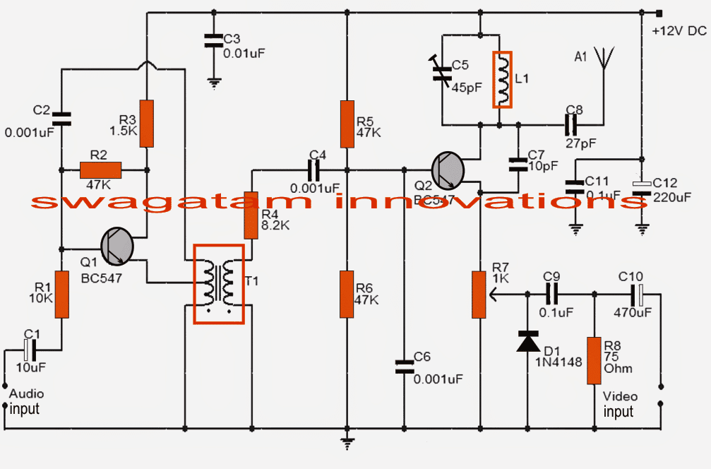
The TV transmitter circuit presented in this post incorporates the European standard FM frequency for audio and Video up-links.
Referring to the circuit below, Q1 is configured as a preamplifier for amplifying the audio input to be modulated.
Circuit Description
Q2 is fundamentally responsible for conducting a couple of important functions: It amplifies the carrier frequency generated by the tank circuit, and also modulates the input over this carrier waves.
The preamplified audio signals from the Q1 stage is fed to the Q2 stage at its base for the intended modulation actions.
As we know all transmitter circuits require a conventional "tank" circuit involving an inductor and few capacitors for generating carrier waves.
Here too a tank circuit becomes imperative and is formed by the insertion of C5, L1. This network essentially generates the crucial carrier waves.
The video signal which needs to be superimposed with the audio signal is applied to the emitter of Q2 through the variable resistor R7 for implementing the intended modulation process.
The composite signal (audio + video) after modulation via the Q2 and the tank circuit stages is further applied to the connected antenna A1 for the final transmission into the atmosphere so that it can be received by a particular TV set in the vicinity.
The proposed TV transmitter circuit requires a well regulated stabilized 12V supply for operating.
Preferably a 12v battery would give better results due to a much cleaner DC free from all possible ripples and noises.
Circuit Diagram
Some Important Points:
Things you need to consider while building this TV transmitter circuit at home:
Preferably use a well designed glass epoxy PCB for this project.
- For the inductor L1 use a super enameled copper wire of 24SWG and wind 4 turns with 6mm diameter over any non conducting former such as paper or plastic.
- T1 may be replaced with any standard audio transformer the type which were commonly used in olden transistor sets and radios at the output amplifier stage.
- The antenna is not much critical, can be any good conductor of electricity, around a foot long, such as a copper wire. You may try different lengths until you get the optimal response from the TV transmitter circuit.
- The operating frequency of this unit could be within 50 and 210MHz.The compatibility of this circuit is well with PAL B/C systems.
- You may have some fun with C8 which may be tweaked a bit for acquiring extreme accuracy with the performance of the circuit.


Comments (20)
good day, it looks like an interisting prpject. How far can the signal go? And is it posible to extend the range?
Thank you Jan, the maximum range is within 10 meters radial.
Range can be somewhat extended by increasing the antenna length or height.
Am interested on interaction about TV Madi circuit
Okay sir thanks so much..
Okay sir, thanks so much,,but, if we vary it out from TV’s frequency, that means we will need a suitable receiver for the frequency..please help.
How do we achieve this aim?
Thanks
You are welcome Sunshine, you may have to tweak the settings of your TV receiver and adjust it according to the transmitter frequency which can be very difficult. There doesn’t seem to be any other feasible option.
Engineer Good morning sir. Happy Sunday.. Long time, I’m glad to meet you here again.
Please is it possible to get video transmitter and its receiver?..please help thanks my esteemed engineer..
Hello Sunshine, a simple video transmitter is explained in the above article. However for a video receiver you will have to use a ready made TV set, because making one can be too complex.
Okay sir… Does it receive on VHF,UHF or VLF? I don’t want everyone around to receive it, unless I authorized them.. Is there any way to protect it? Thanks
Sunshine, The operating frequency can be modified by adjusting L1, C5, which means we can customize the frequency as per our own required specifications.
Dear sir, please sir my CRT tv panel starts and immediately goes to standby mode when powered on. If I off the power button, and switch on again, it starts again, and then off.
Please sir, what could be the problem?
Thank you
Many things can cause it..
1. If the 110v is not complete
2. Frame coil or frame ic.
3. Boaster cap.
4. Over voltage from power section.
5. Low voltage from power section.
Many things can cause it even line transformer….
LG TV and Samsung TV normally do this.. If you can’t trace the fault send to an advanced engineer..thanks
Hi Godfrey, without checking practically it can be difficult to judge the fault.
Okay sir, but what are the possible causes for such fault?
When I press the power button, the television starts with d green LED indicator, and within few seconds, it goes to standby mode with the red LED indicator.
If I switch off the power off the power button, and switch on again, the television starts again, and goes back to standby mode as well after few seconds
Godfrey, The issue may be related specifically to the TV circuit, so only a TV technician will be able to answer that by checking your TV practically.
Is this digital TV transmitter?
sir, i have made this given circuit successfully but could you please tell me about what to attach at the video and audio inputs of this perfectly designed tv transmitter circuit?,also tell me is it compatible for any simple now-a-days telivisions?,also tell me that is there any need for any attachment in the recieving tv set such as an antenna? ,please help me,for its reply i shall be ever obliged to you.thank you
you can connect an audio video signal from your DVD player into the shown inputs
a 3 meter long wire may be required as antenna for the TV.
look for an old transistor MW radio, you can get it from a TV/radio mechanic shop, inside the radio you will hopefully see this small transformer close to the speaker wire outputs.
simply remove it and use it here.
According to me it can be done in the following way.
Configure the IC555 in a monostable MV circuit mode, and feed its pin#5 with a music input after passing it through a low pass filter.
This might just work.
I hope you understood the method?