In this post I have explained a simple line laser controlled motor driver circuit, which works by responding to a precision horizontal laser line, generated from a line laser level device, and automatically adjusts the alignment of the connected tool or the job work with extreme perfection and accuracy.
What is Line Laser
The line laser equipment is an high precision electronic replacement of the carpenters age old spirit level aligner.
The line laser device is actually an advanced laser emitting equipment which can generate a 360° high precision illuminated horizontal laser line, for providing a calibrating reference to all industrial or constructional engineering jobs, so that the end result of the job is perfectly straight and aligned without a slightest bit of error.
The circuit was requested by one of the dedicated readers of this blog, Mr. Rafal.
The detailed discussions regarding the working procedure of the line laser controlled motor can be learned from the following paragraphs:
Design Objective
Mr. Rafal: I'm very new to this. I've done some research in the last few weeks and haven't found exactly what I need.
I will be grateful for any help. I attach a photo of my idea. I want to control two 12 V DC motors with a laser level.
The line laser level will signal the receivers.
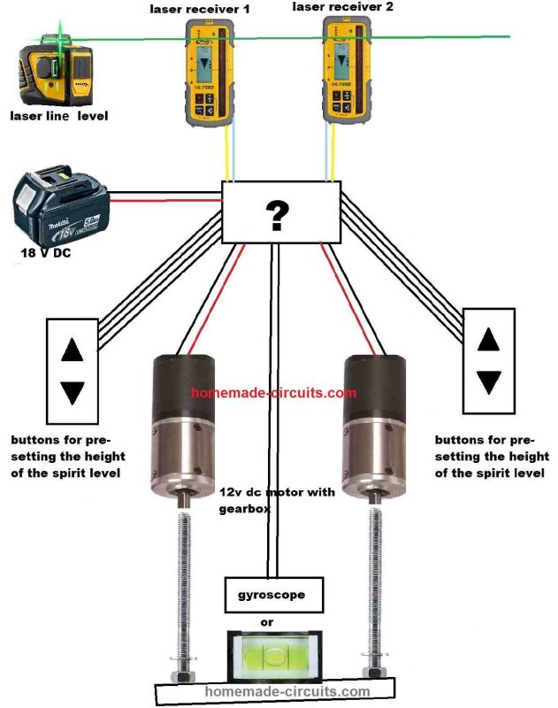
This signal will then have to control the direction of the 12 V DC motor. The motor rotates the threaded rod back and forth to adjust the height of the tool.
From what I discovered, there would be several photodiodes connected in parallel, one set to detect the laser above zero level and the other below that level. The null level is just some kind of pause between the photodiodes to keep the system from waking up. Laser sensor without display. I only gave a pictorial photo.
I need an H bridge circuit, but all found by me are to be used with an Arduino system. If necessary, I can purchase a ready-made bridge for a reasonable price of up to $ 30
Ideally this would work with both red and green lasers, but the wavelengths are so different that I doubt it could be done and it wouldn't work across the entire light spectrum.
Initially, I would like to set the level of this beam attached to the engines with the up-down buttons. I would be delighted if the second motor would then level itself with the gyroscope while setting it up, but without the Arduino it might be very difficult.
I feel what I am trying to do is so simple that I can get away without using Arduino. And I insist on an analog, due to the difficult conditions at a construction site and it seems to me that the more electronics, the more unreliable the device.
It will only work indoors, and the laser distance is max 10m. The motor I found at the beginning has a large current consumption of 200mA max 2.19 A, but also a large torque.
Power 18 V DC from a Makita battery.
Thanks in advance for any suggestions.
Greetings from Poland
Rafal
Swag: I have a confusion about the working of the motor shafts. The threaded screw on both the motors will push the tool, but it cannot pull it back? How does that work out?
Is it possible to implement the same with a single motor?
Mr. Rafal: Lower leveling straightedges would be perhaps 70 cm, only for small rooms, e.g. a toilet so that you can enter through a door.
Machine without drive, hand-pulled, only leveling straightedges. In the video, the two yellow objects on masts are laser detectors rigidly attached to the straightedges.
The laser is standing somewhere further away and it produces a horizontal line.
The motors would be attached to a cart and the threaded screw to leveling straightedges with laser detectors. There must be two motors to level both sides, but it's a mirror image.
The only common part would be a two-channel H-bridge as if I were doing it from a ready-made module and possibly a gyroscope, but that's a dream :).
It is important that there are button for left and right motors revolutions.
The procedure is this. I hang the laser for example 2 m above the designated floor level. I measure out 2 meters from the laser beam to the bottom edge of the straightedges.
I regulate the height pressing buttons the switches right-left so that it is equal to 2 meters to the bottom edge of the straightedges. I put the detectors on the masts so that the laser beam is at zero level between the photodiode sections. And the rest will do itself 🙂
In the attachment I put a drawing of the detector operation.
Rafal
Circuit Design
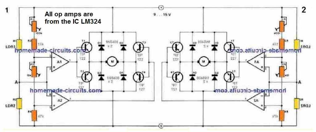
Looking at the figure above, two such identical circuit stages will be required for detecting and correcting the associated motor controlled tool with respect to the laser line straightness accuracy.
The two identical stages are mirror images of each other as shown below:
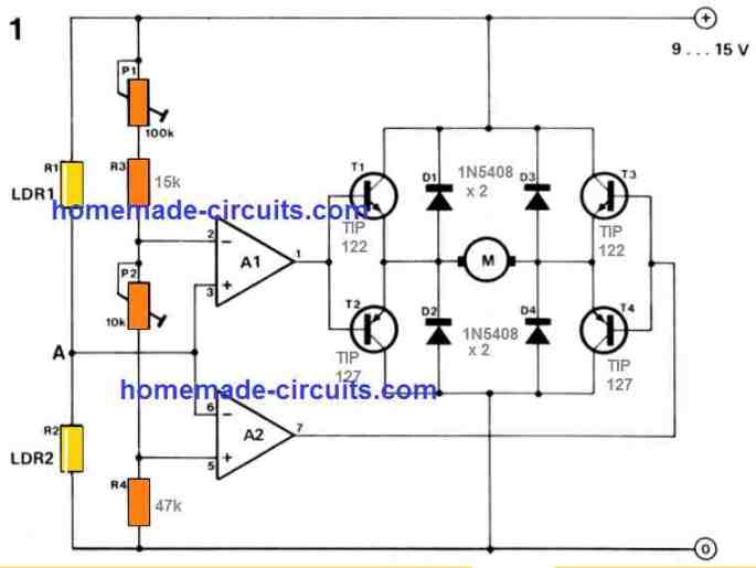
The circuitry is fairly straightforward. It works with a window comparator which ensures that the drive motors are non-operational so long as the pair of LDRs are exposed with the identical laser line brightness.
One half supply voltage is then generated on the non-inverting input of A1 and to the inverting input of A2.
As soon as a deflection in the laser line is detected (which can happen if the motor controlled tool is not aligned straight), the brightness impacting LDRs R1 and R2 changes.
In this situation, the input voltage to the window comparator drifts away from half the supply voltage. This situation causes the comparator output to command the motor bridge network to move the motor in the clockwise or anticlockwise directions.
Transistors T1 . . . T4 are configured like a bridge network to enable switching of the motor in forward and reverse directions depending on the LDR illumination or the laser line deviation angle.
Diodes D1 . . . D4 are positioned to cancel voltage peaks generated during the time the motor is avtive and running. The function of the Preset potentiometers P1 and P2 is for facilitating the alignment adjustments.
These are fine-tuned to ensure the motor is completely shut off and inactive as long as the relevant LDR pair is exposed to the exact same laser light brightness.
Let's say for example, due to incorrect alignment of the motor controlled tool, the laser line tilt causes the light to reduce on LDR R2 than LDR R1. This will result in the voltage at point A to rise above half the supply voltage.
In this situation, the A1 op amp output becomes high, forcing the transistors T1 and T4 to operate. This in turn causes the motor to rotate in the relevant direction. This action automatically shifts the connected tool in a straight line until its horizontal alignment accuracy coincides with the laser line accuracy .
Conversely, if we assume the tool to be tilted with the opposite orientation such that illumination of the LDRs are opposite to the discussed above, causes the voltage at point A to drop below half the supply voltage. This condition triggers output A2 op amp to go high such that T3 and T2 become operational.
This results in the motor now running in the opposite direction, in an attempt to correct the alignment of the tool in the relevant direction until it becomes perfectly straight coinciding with the laser line horizontal accuracy.
Up/Down Button
The up down buttons for initially presetting the height of the spirit level can be simply implemented by wiring push-button switches in parallel to each of the LDRs.
LDR Installation
For getting the correct response from the LDRs, the left right pairs must be installed inside a tube like enclosure such that they are able to "see" only the laser illumination, and not any other ambient light.
The idea can be witnessed in the following image:
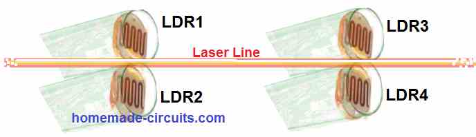
Here, we can see that the LDRs are positioned very close to each other, which ensure that when the laser line is at the exact center, some portion of the both the LDR pairs get illuminated by the laser light uniformly.
The front of the LDR enclosure could be covered with a diffused lens, so that the laser illumination could be diffused inside over the respective LDRs uniformly.


Comments
Greetings dear Swagatam. I watch you and love you. We install pv panels on the roofs. We pull the rope to make it smooth. The wind pushes the rope. It’s crooked. For my crawler marker, I need a laser tracking circuit. Is there a circuit that you would recommend?
Thank you so much Mehmet, I appreciate your kind words!
I do not have a laser tracking circuit with me right now, but if you tell me the working specifications, then I may try to design it for you. Please let me know.
Greetings dear Swagatam. I want to draw a straight line on factory roofs. I need a laser tracking circuit for this. I will buy a mini tracked robot from China. I will also attach the circuit to it. I will attach a felt pen to the robot. Let him draw while walking. So I’ll lay the panels properly.
I will place the laser module at the other end of the factory roof. I will install two separate motors on two pallets, left and right. The motors will be activated by the signal from the circuit. The circuit will produce a signal by following the laser. It will produce a signal as long as it sees the laser. If it does not see the laser or sees it poorly, it will reduce the signal. Thus, the engines will run fast or slow. The robot will go straight.
Dear Swagatam, thank you for your interest. I am very pleased. Your last advice will be useful to me with a small revision. I will use this in my project. Greetings.
You are most welcome Mehmet,
Let me know if you face any problems with the suggested design…
🙋♂️
OK, thanks for the description, however I cannot still interpret the whole setup in my mind. I think only a block diagram can help me to design the circuit correctly.
In the meantime you can consider modifying the following concept as per your application specs. Let me know if it seems suitable or not:
https://www.homemade-circuits.com/simple-line-follower-vehicle-circuit-using-op-amps/
Thank you Mehmet,
Can you please tell how the required circuit is supposed to work for you?
Hello! My compliments, for sharing your knowledge. I noticed that the device is very nervous during use, even with the use of reduction in both engines. I realize that for my use, I need hysteresis(delay), between movements. It would be possible or complicate a lot. It works quite well, moreover. Thanks for posting.
Thanks so much for your kind words and glad you found the post helpful!
I think the hysteresis can be added in the following manner.
First, connect the pin#3 of A1 and pin#6 of A2 separately to the positive supply via individual 10k resistors.
Next, connect the calculated hysteresis resistor between pin#1 and pin#3 of A1, and between pin#7 and pin#6 of A2.
Alternatively, you can simply connect a series 10k resistor between the A1, A2 outputs and the BJT bases, followed by a 100uF/25V capacitor between the bases of the BJTs and ground. In this case make sure the H-bridge BJTs are Darlington type.
Hello, we need a laser receiver. Can you make it?
Sorry, I cannot make it for you, I can only help with the circuit details.
Hello Swagatam. I want to control two linear motors with two Topcon LS-B100s. I want to make the level of the concrete floor smoothly with the machine I want to build. I thought linear motor might make more sense since hydraulic systems are more complex, how can I do that? can you help me?
Hello Ali, it seems to be a high precision mechanical instrument which will require a lot of expertise in the field. Unfortunately, it is something which is beyond my level of expertise, so I won’t be able to offer much help on this.
Thank you for this information. I hope i will do the project i think….
You are most welcome!