In this post I will show how to construct a customizable Arduino based IR (infrared) based wireless remote control switch, which consists of IR remote and a receiver, you may modify according to your needs. In the later part of the article I have explained about an upgraded foolproof version of an IR remote control which will respond only to an uniquely assigned frequency.
If you are above beginner level you can accomplish it with ease. The proposed circuit illustrated here just has three controls on remote and 3 relays on receiver end. You may modify the code and circuit diagram to fulfill your needs.
You’ll need two Arduino boards, which act as remote and another act as receiver. I would recommend Arduino pro mini for this project, since the sizes of them are pretty small and the overall size of the remote could be shirked.
You may use 3.3V based Arduino pro mini for remote so, that you can be powered with two button cell or two AA size batteries, according to your needs.
The IR transmitter circuit has 3 push to on buttons and an IR LED for sending commands to receiver. Each button has programmed with unique hexadecimal code, the same hexadecimal code is programmed on receiver side too.
When a button is depressed the IR LED sends out the hexadecimal code to receiver, the receiver will recognize which of the button is pressed and it switches the corresponding relay ON/OFF.
The proposed remote uses RC5 protocol for communicating with receiver; you may change everything by modifying the code.
If you are just beginner in Arduino, you can still accomplish it just follow the diagram and upload the code without modifying.
The circuit and program:
Arduino Remote Transmitter:
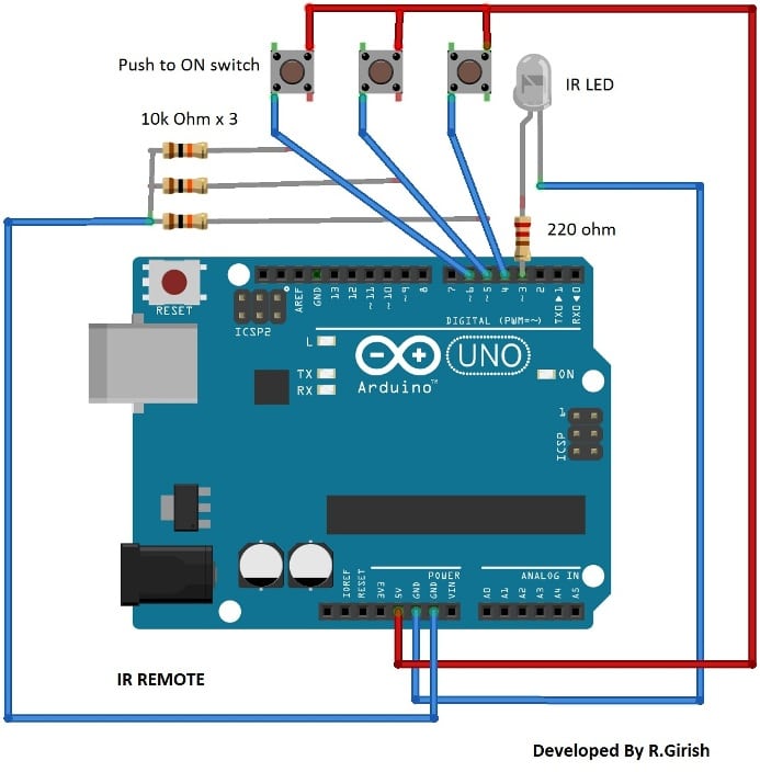
The above circuit illustrates how to build the Arduino IR remote transmitter.
The three 10K resistors are pull down resistors, which prevent accidental triggering of the remote due to static charge and a 220ohm current limiting resistor is employed for IR LED.
Program for Remote Transmitter:
//---------Program developed by R.Girish--------//

#include <IRremote.h>

IRsend irsend;

const int button1 = 4;

const int button2 = 5;

const int button3 = 6;

void setup() {

pinMode(button1, INPUT);

pinMode(button2, INPUT);

pinMode(button3, INPUT);

}

void loop()

{

if (digitalRead(button1) == HIGH)

{

delay(50);

irsend.sendRC5(0x80C, 32);

delay(200);

}

if (digitalRead(button2) == HIGH)

{

delay(50);

irsend.sendRC5(0x821, 32);

delay(200);

}

if (digitalRead(button3) == HIGH)

{

delay(50);

irsend.sendRC5(0x820, 32);

delay(200);

}

}

//---------Program developed by R.Girish--------//
Arduino Receiver:
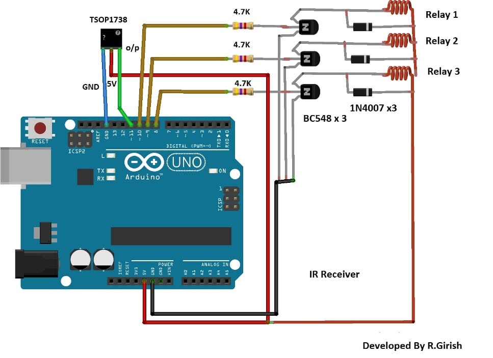
The IR Arduino receiver circuit as shown above consists of TSOP1738 sensor few transistors, current limiting resistors for transistor, relays and diodes for absorbing high voltage spike from relay coils.
The circuit diagram is self explanatory.
Program for Arduino receiver:
//-----------------Program developed by R.Girish-----------//

#include<IRremote.h>

int input = 11;

int op1 = 8;

int op2 = 9;

int op3 = 10;

int intitial1;

int intitial2;

int intitial3;

IRrecv irrecv(input);

decode_results dec;

#define output1 0x80C // code received from button A

#define output2 0x821 // code received from button B

#define output3 0x820 // code received from button C

void setup()

{

irrecv.enableIRIn();

pinMode(op1,1);

pinMode(op2,1);

pinMode(op3,1);

}

void loop() {

if (irrecv.decode(&dec)) {

unsigned int value = dec.value;

switch(value) {

case output1:

if(intitial1 == 1) {

digitalWrite(op1, LOW);

intitial1 = 0;

} else {

digitalWrite(op1, HIGH);

intitial1 = 1;

}

break;

case output2:

if(intitial2 == 1) {

digitalWrite(op2, LOW);

intitial2 = 0;

} else {

digitalWrite(op2, HIGH);

intitial2 = 1;

}

break;

case output3:

if(intitial3 == 1) {

digitalWrite(op3, LOW);

intitial3 = 0;

} else {

digitalWrite(op3, HIGH);

intitial3 = 1;

}

break;

}

irrecv.resume();

}

}

//--------------Program developed by R.Girish-----------//
By following the above explanations you can accomplish three controls, if you want to add more controls and relay, you need to edit the code and circuit diagram.
You can assign output and input for unused pins in the receiver and remote in the program and connect number of transistor and relay for the respective pins in receiver and similarly connect number of switches and pull down resistor in remote.
You can use random hexadecimal code for assigning more number of buttons.
For example: 0xA235, 0xFFFF, 0xBA556 and so on. And also add the same hexadecimal value in receiver code too. For example: #define output4 0xA235, #define outout5 0xFFFF and so on.
Making a IR Remote Control with Unique Frequency
In the above sections I have explained about a simple IR remote control that will work with any IR remote transmitter.
In the following article I have explained how to make an upgraded version of the above concept for a foolproof control of the home appliances using arduino microcontroller, which will work with a unique frequency and never operate with common IR handset.
Foolproof IR Remote Control
This circuit can turn on/off your gadgets using TV remote’s unused buttons or any other unused remote that may be lying in your junk box for ages.
The motto of this project is to help physically challenged persons, and help them to access the ON/OFF switching of the basic home appliances such as fans or lights independently.
The second objective is to enable the user to control the gadgets “Like a boss” without having to move from his or her existing position.
The circuit utilizes traditional IR based communication between transmitter and receiver.
This circuit is cent percent foolproof to other IR remotes, and other IR sources and less susceptible to errors.
The major problem with non-microcontroller based IR remote control circuit, which is found around the internet, is that it could turn ON/OFF with any IR based remote and can only control one device at an instant and also more susceptible to errors.
This circuit overcomes above specified issues, and we can control several gadgets on one remote and assign keys for specific gadgets.
Before proceeding this project you need to download the library files for arduino form this link and follow the instruction given below: github.com/z3t0/Arduino-IRremote
Instructions:
1) Click “clone or download” button form the given link and hit “Download ZIP”.
2) Extract the file and move “IRremote” folder to your library folder of Arduino.
3) Delete “RobotIRremote” folder from your arduino library. “RobotIRremote” has similar definition of “IRremote” library which clash and not able to upload the code to Arduino so, deletion/removal is mandatory.
By duplicating the above instruction your Arduino IDE software is ready for any/most of the IR based projects.
Assign keys for remote:
In our TV remote each key has unique hexadecimal code, which is used to recognize which key is pressed for an operation. Before uploading the final code to Arduino, you need to find what the hexadecimal codes for your keys are.
To do this construct the following circuit in breadboard and follow the instruction.
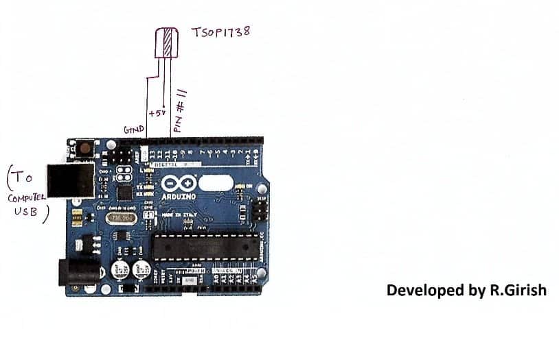
1) Open Arduino IDE and upload example code “IRrecv Demo”
2) Open serial monitor and press the key on remote that you want to use.
You’ll see hexadecimal code pop up as soon as you press the key. That’s the hexadecimal code for that particular key.
3) Do the same for other two keys (3 keys are given in this project for controlling 3 devices)
· We are going to use these hexadecimal codes in the main program and upload to arduino.
Program:
//-----------------Program developed by R.Girish-----------//

#include<IRremote.h>

int input = 11;

int op1 = 8;

int op2 = 9;

int op3 = 10;

int intitial1;

int intitial2;

int intitial3;

IRrecv irrecv(input);

decode_results dec;

#define output1 0x111 // place your code received from button A

#define output2 0x112 // place your code received from button B

#define output3 0x113 // place your code received from button C

void setup()

{

irrecv.enableIRIn();

pinMode(op1,1);

pinMode(op2,1);

pinMode(op3,1);

}

void loop() {

if (irrecv.decode(&dec)) {

unsigned int value = dec.value;

switch(value) {

case output1:

if(intitial1 == 1) {

digitalWrite(op1, LOW);

intitial1 = 0;

} else {

digitalWrite(op1, HIGH);

intitial1 = 1;

}

break;

case output2:

if(intitial2 == 1) {

digitalWrite(op2, LOW);

intitial2 = 0;

} else {

digitalWrite(op2, HIGH);

intitial2 = 1;

}

break;

case output3:

if(intitial3 == 1) {

digitalWrite(op3, LOW);

intitial3 = 0;

} else {

digitalWrite(op3, HIGH);

intitial3 = 1;

}

break;

}

irrecv.resume();

}

}

//--------------Program developed by R.Girish-----------//
NOTE:
In the program:
#define output1 0x111 // place your code received from button A
#define output2 0x111 // place your code received from button B
#define output3 0x111 // place your code received from button C
· Place your 3 unique codes from your remote in this place of 111, 112, and 113 and upload the code. Hexadecimal codes will be from 0 to 9 and A to F, for example: 20156, 26FE789, FFFFFF.
· Place your code with “0x” (zero x).
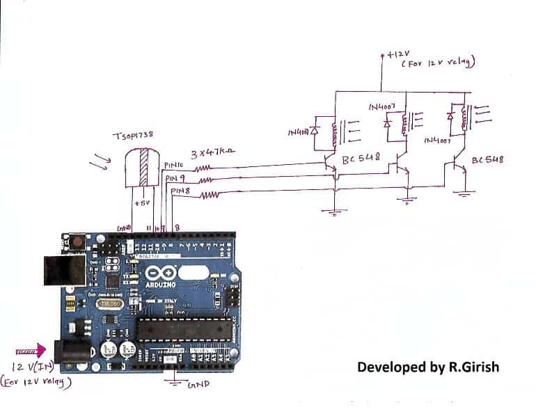
Circuit diagram:
· Pressing key trips the relay ON and by pressing again it will turn off the relay.


Comments
I am looking for a 6 channel IR remote control with 7 non latching relays. I want each of the 6 buttons to operate a corresponding relay and the 7th relay to operate when any button is pressed. I would be prepared to pay for a design. I have found similar online but they are all latching.
Six channel IR remote can be readily procured from any online electronic store. The 7th relay can be put externally, and the supply to its coil can be fed through separate diodes, whose input side may be integrated with supply voltage arriving from the rest of the 6 relays, so that when any of the relay activates, the 7th relay also activates.
I have found many online and even bought a few but they are all latching. I don’t know how to modify them.
there’s a small switch on the PCB, which needs to set up to implement either a latching mode or a temporary ON mode
I don’t know if there is a facility to send photographs to you but there is no switch on this Pcb’s
If you couldn’t find the switch then probably there’s no such facility available on your circuit board. Actually this mentioned switch is commonly available on RF remote control units, I am not sure about the IR type remote controls. In such a situation you may have diagnose the transistor stage of the relay driver and then modify the circuit so that the latching feature is disabled.
Hello,
interesting topic. 🙂
I would like to ask if I can use the hex code found in this way to build my own Attiny85-based remote controller?
I would like to build a remote controller only with a sleep timer function. (this function is missing on my TV)
Thanks for the reply…
Hi sorry, I am not good with Arduino stuff, so can’t suggest much!!
Could you supply circuit diagram, parts name, used code, library name for controlling celling fan’s speed by infrared remote and Arduino UNO? Hence I will be grateful to you.
Thanks, If it is possible I’ll surely try and update it here!