• Skip to main content
  • Skip to primary sidebar

Homemade Circuit Projects

Need circuit help? Post them in the comments! I've answered over 50,000!

Blog | Categories | About | Contact | Calculators-online
You are here: Home / Datasheets and Components / High Voltage Transistors BUX 86 and BUX 87 – Specifications

High Voltage Transistors BUX 86 and BUX 87 – Specifications

Last Updated on January 8, 2024 by Swagatam Leave a Comment

In this article we are going to make an effort to understand the technical specs of the BJTs BUX86 and BUX87 which are high voltage complementary paired transistors.

Table of Contents
  • Introduction
  • Technical Specifications and Electrical Tolerances

Introduction

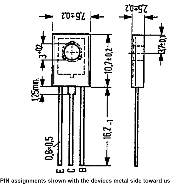
The Bux 86 and BUX 87 are typically high voltage switching transistors with silicon epibase. They come in TO-126 package and are NPN types.

These devices are especially known for their outstanding short switching characteristics and for having a high dielectric strength.

The main applications using these devices can be found with TV circuits, electronic ballasts, converters, SMPS power suppliers etc.

Technical Specifications and Electrical Tolerances

  • The maximum tolerable electrical parameters for BUX 86 and BUX 87 may be understood with the following points:
  • Maximum collector to emitter voltage for BUX 86 is 400 volts and 450 Volts for BUX 87.
  • Maximum tolerable collector current for is 500 mA for both the devices.
  • Maximum tolerable instantaneous peak current across collector and emitter is 1 Amp for <2 ms for both the devices
  • Maximum tolerable constant base current is 200 mA for both the devices.
  • Maximum peak instantaneous base tolerable current is 300 mA for both the devices.
  • Maximum power dissipation must not exceed 20 watts for both the devices
  • Typical Static characteristics @ 25 degree ambient temperature of BUX 86 and BUX 87 transistors are listed below:
  • Collector cut-off current is <0.1 mA
  • Typical forward current gain for both the devices is around 50
  • Collector to emitter saturation voltage is less than 1.5 V @ 100 mA collector current and 10 mA base current.
  • Base to emitter saturation voltage is less than 1 volts @ 200 mA collector current and 20 mA base current.
  • Maximum frequency handling capacity is 20 MHz for both the devices
  • Turn ON switching speed is 0.25 micro-second.
BUX 1

You'll also like:

  • 1.  LM567 Tone Decoder IC Features, Datasheet and Applications
  • 2.  IRF510 Datasheet [100V, 5.6 Amp, N-Channel MOSFET]
  • 3.  Alarm Signal Generator IC ZSD100 Datasheet, Application
  • 4.  OBD2 Connector Pinout, Datasheet
  • 5.  High Voltage Transistor MJ11021(PNP) MJ11022 (NPN) Datasheet – Complementary Pair
  • 6.  Arduino LCD KeyPad Shield (SKU: DFR0009) Datasheet

About Swagatam

I am an electronics engineer with over 15 years of hands-on experience. I am passionate about inventing, designing electronic circuits and PCBs, and helping hobbyists bring their projects to life. That is why I founded homemade-circuits.com, a website where I share innovative circuit ideas and tutorials. Have a circuit related question? Leave a comment.... I guarantee a reply!

Previous Post: « How to Make a Remote Control Circuit from a Remote Bell
Next Post: How to Understand and Use IC 4093 NAND Gates, PinOuts »

Reader Interactions

Need Help? Please Leave a Comment! We value your input—Kindly keep it relevant to the above topic! Cancel reply

Your email address will not be published. Required fields are marked *

Primary Sidebar

Subscribe to New Circuit Ideas

Categories

  • Arduino Projects (87)
  • Audio and Amplifier Projects (132)
  • Automation Projects (17)
  • Automobile Electronics (101)
  • Battery Charger Circuits (83)
  • Datasheets and Components (104)
  • Electronics Theory (143)
  • Free Energy (37)
  • Games and Sports Projects (11)
  • Grid and 3-Phase (19)
  • Health related Projects (25)
  • Home Electrical Circuits (12)
  • Indicator Circuits (14)
  • Inverter Circuits (87)
  • Lamps and Lights (142)
  • Meters and Testers (69)
  • Mini Projects (46)
  • Motor Controller (64)
  • Oscillator Circuits (27)
  • Pets and Pests (15)
  • Power Supply Circuits (108)
  • Remote Control Circuits (50)
  • Security and Alarm (64)
  • Sensors and Detectors (101)
  • Solar Controller Circuits (59)
  • Temperature Controllers (42)
  • Timer and Delay Relay (49)
  • Transmitter Circuits (29)
  • Voltage Control and Protection (37)
  • Water Controller (36)

Calculators

  • Battery Back up Time Calculator
  • Capacitance Reactance Calculator
  • IC 555 Astable Calculator
  • IC 555 Monostable Calculator
  • Inductance Calculator
  • LC Resonance Calculator
  • LM317, LM338, LM396 Calculator
  • Ohm’s Law Calculator
  • Phase Angle Phase Shift Calculator
  • Power Factor (PF) Calculator
  • Reactance Calculator
  • Transistor Astable Calculator
  • Transistor base Resistor Calculator
  • Voltage Divider Calculator
  • Wire Current Calculator
  • Zener Diode Calculator
  • Filter Capacitor Calculator
  • Buck Converter Calculator
  • Boost Converter Calculator
  • Solar Panel, Inverter, Battery Calculator
  • Wire Current Calculator
  • SMPS Transformer Calculator
  • IC SG3525, SG3524 Calculator
  • Inverter LC Filter Calculator

People Also Search

555 Circuits | 741 Circuits | LM324 Circuits | LM338 Circuits | 4017 Circuits | Ultrasonic Projects | SMPS Projects | Christmas Projects | MOSFETs | Radio Circuits | Laser Circuits | PIR Projects |

Recent Comments

  • Swagatam on Understanding SG3525 IC Pinouts
  • Dan on Understanding SG3525 IC Pinouts
  • Swagatam on High Current Wireless Battery Charger Circuit
  • Swagatam on Timer Based Cell Phone Charger Circuit
  • Nitesh Agrawal on Timer Based Cell Phone Charger Circuit

Company

  • Privacy Policy
  • Cookie Policy
  • About Me
  • Contact
  • Disclaimer
  • Copyright
  • Videos
  • Sitemap

Social Profiles

  • Twitter
  • YouTube
  • Instagram
  • Pinterest
  • My Facebook-Page
  • Quora
  • Stack Exchange
  • Linkedin
  • © 2025 · Swagatam Innovations