In this post I have explained through two examples how to build a simple110 V or 220 V AC light dimmer circuit for controlling light intensity with pot, using the principle of triac phase chopping.
A 220V dimmer switch circuit is basically a triac/diac based AC mains voltage regulator circuit which can be used for controlling the intensity of an incandescent bulb.
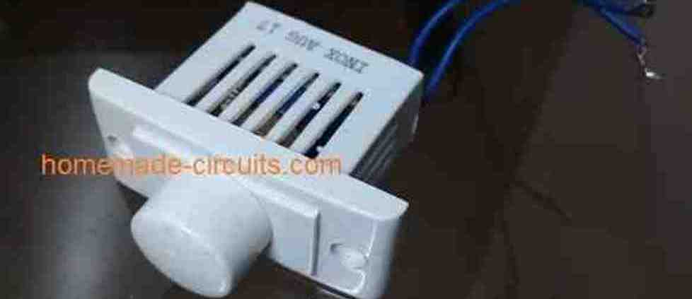
What are Triac Dimmers
We have already seen in many of my earlier articles how triacs are used in electronic circuits for switching AC loads.
Triacs are basically devices which are able to switch ON a particular connected load in response to an external DC trigger.
Though these may be incorporated for complete switch ON and complete switch OFF procedures of a load, the device is also popularly applied for regulating an AC, such that the output to the load may be reduced to any desired value.
For example triacs are very commonly used dimmer switch applications where the circuit is designed to make the device switch in such a manner that it conducts only for a particular section of the AC sine wave and remains cut OFF during the remaining parts of the sine wave.
This result is an corresponding output AC which has an average RMS value much lower than the actual input AC.
The connected load also responds to this lower value AC and is thus controlled to that particular consumption or resultant output.
This is what exactly happens inside electrical dimmer switches which are normally used for controlling
incandescent lights.
Warning: All the circuits I have explained below are connected directly with the mains AC, therefore is extremely dangerous to touch while powered ON and in uncovered condition.
Circuit Diagram of a Simple AC Light Dimmer
Working Video Clip:
Simple 220V, 120V AC Light Dimmer Switch Circuit
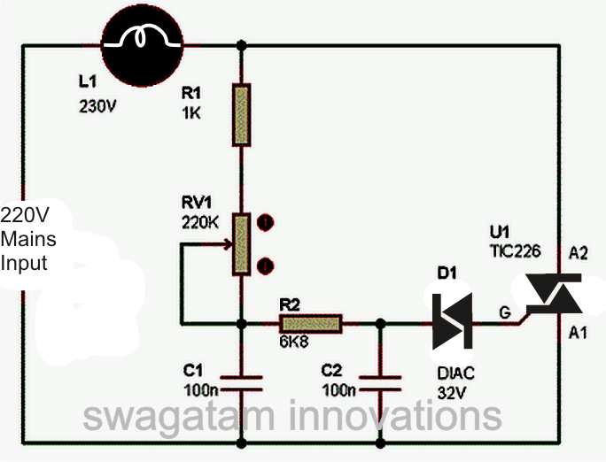
The circuit diagram shown above is an classic example of a AC light dimmer, where a triac has been utilized for controlling the intensity of light.
When AC mains is fed to the above circuit, as per the setting of the pot, C2 charges fully after a particular delay providing the necessary firing voltage to the diac.
The diac conducts and triggers the triac into conduction, however this also discharges the capacitor whose charge reduces below the diacs firing voltage.
Due to this the diac stops conducting and so does the triac.
This happens for each cycle of the mains AC sine wave signal, which cuts it into discrete sections, resulting in well tailored lower voltage output.
The setting of the pot sets the charge and the discharge timing of C2 which in turn decides for how long the triac remains in a conducting mode for the AC sine signals.
You might be interested to know why C1 is placed in the circuit, because the circuit would work even without it.
It's true, C1 is actually not required if the connected load is a resistive load like an incandescent lamp etc.
However if the load is an inductive type, the inclusion of C1 becomes very crucial.
Inductive loads have a bad habit of returning a part of the stored energy in the winding, back into the supply rails.
This situation can choke up C2 which then becomes unable to charge properly for initiating the next subsequent triggering.
C1 in this situation helps C2 to maintain is cycle by providing bursts of small voltages even after C2 has completely discharged, and thus maintains the correct switching rate of the triac.
Triac dimmer circuits have the property of generating a lot of RF disturbances in the air while operating and therefore an RC network becomes imperative with these dimmer switches for reducing the RF generations.
The above circuit is shown without the feature and therefore will generate a lot of RF which might disturb sophisticated electronic audio systems.
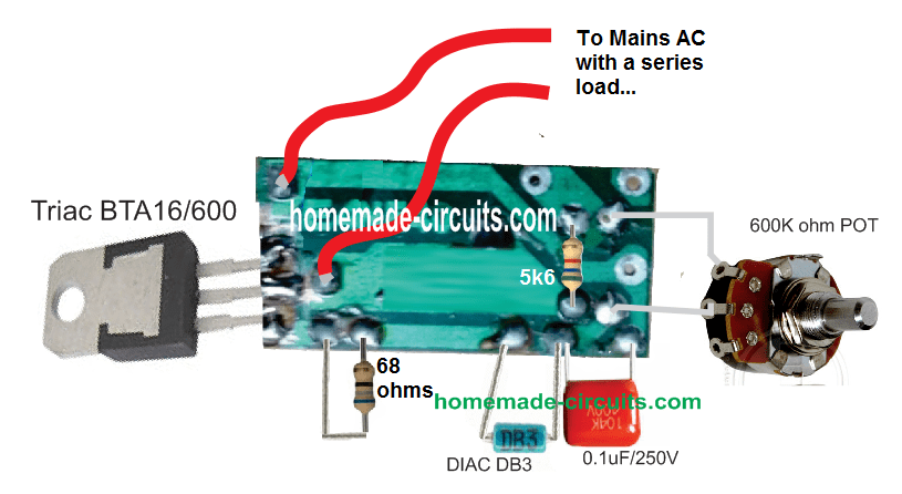
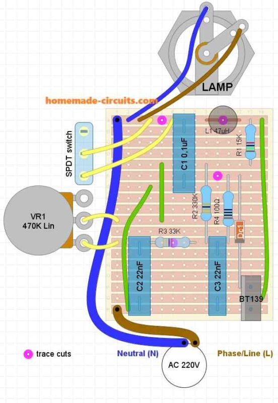
PCB Layout and Connection
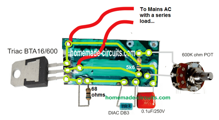
Track Layout Details
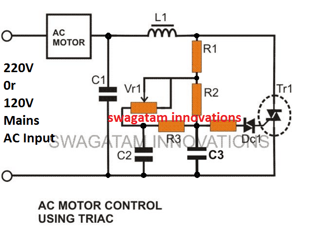
Improved Design
The AC light dimmer circuit illustrated below incorporate the necessary precautions for subsiding the above issue.
This enhanced design also makes it more favorable with high inductive loads such as motors, grinders etc.
This becomes possible due to the inclusion of C2, C3, R3 which allows the diac to be fired with consistent short burst of voltage instead of a abruptly switching pulses, which in turn allows the triac to be fired with smoother transitions, causing minimum transients and spikes.
Circuit Diagram of an Improved AC 220V Light Dimmer
Strip Board Connection Diagram
Parts List
- C1 = 0.1u/400V (optional)
- C2, C3 = 0.022/250V,
- R1 = 15K,
- R2 = 330K,
- R3 = 33K,
- R4 = 100 Ohms,
- VR1 = 220K, or 470K linear
- Diac = DB3,
- Triac = BT136
- L1 = 40uH (optional)
SCR AC Light Dimmer
An adjustable RC-type phase-delay AC light dimmer circuit is shown below which consists of R2. R3, and C1.
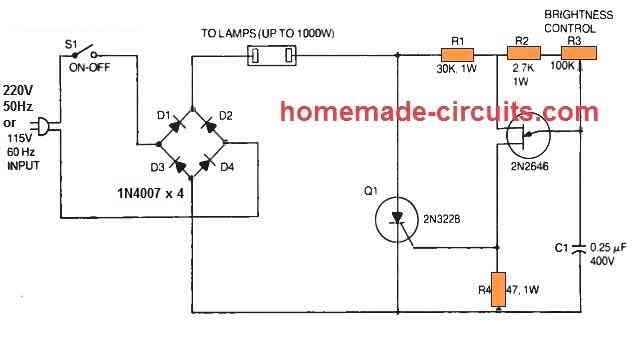
The capacitor C1 fixes the time period where a 2N2646 unijunction transistor (Q2) produces a triggering gate trigger pulse to turn on the 2N3228 SCR (Q1).
By some manipulation of the light-duty control, R3 pot the user is able to change the SCR output across a large range.
In the phase-control circuit, resistor R2 works like a security unit that inhibits rheostat R1 from getting fixed at 100 % anode voltage of the UJT.
This specific rule is applied here to regulate the illumination level of the incandescent lamps, whether as a single lamp or many in parallel as high as to 1000 watts.
In this design, a full-wave bridge rectifier is built using 4nos of 1N4007 silicon power diodes (D1 to D4) that supply rectified power-line voltage for the SCR and the lamp.
Due to the full-wave output from the bridge, it becomes possible for the SCR to take care of both half-cycles of the AC line voltage.
The phase-shift system is sensitive to frequency and has been designed for 60 Hz mains input only.
Therefore the circuit is not going to work with fluorescent lamps and should not be plugged into these.
The 2N3228 SCR 5-amps. 200-volts. but higher-powered SCRs could be replaced for high current applications, and the UJT 2N2646 section of the schematic could be kept unchanged.
Besides SCR circuit is supposed to be used like an AC light dimmer, this circuit can be employed likewise as a heater or oven controller.


Questions & Answers
Hi Swagatam, I want to create a dimmer switch for 3 series light bulbs 50W each, can I use this same circuit? Thanks in advance. By the way, this is a very good article, I've been searching for other circuit, and this is the best and very informative one.
Hi Joana,
Yes you can the same circuit for 3 bulbs in series, however putting bulbs in series will make their brightness low.
Hi, thank you for your very quick reply, what if I make the connection of the bulbs parallel? Also will it last for long hours? I plan to install it permanently on my house. 😀
yes putting them in parallel would be the correct approach, however the triac won't hold more than 200 watts without heatsink, and 500w with heatsink attached, so be careful about that.
if the above parameter is taken care of then it would be a permanent thing, no issues 😉
1500w grinder machine to can i use bta 24 triac?
use BTA40/600
i need to control kitchen machine ac motor 220/600w/60hz with 6 speed are above circuit do it or please tell me how to do it
plese, need to control kitchen machine 230/6oow/60hz need the circuit to control
Try the second circuit given in the above article.
Use the following parts:
R1 = 15K
R2 = 330K
R3 = 22K
VR1 = 220K
diac resistor = 47 ohm
diac = DB-100
Triac = BTA41/600.
C2, C3 = 0.1uF/250V
C1 = 0.1uF/400V
are this componant work with ac motor 600w 60hz
need to work with ac 600 watt 60hz ac motor use BTA40/600 or what
i want to control Tubelight with TRIAC switch. Is possible?
i am going to connect the gate of the TRIAC to Arduino Board..
Is possible? Reply me
Sorry, no ideas about it.
Hi Sir –
I would like to use a dimmer type switch to control the input from the main of a transformer which is rated at 2500W at 20amps.
Would this circuit work & how would I spec out the components properly? Any help would be greatly appreciated.
Hi Brad,
You can try the second circuit, with the following pats:
R1 = 15K
R2 = 330K
R3 = 22K
VR1 = 220K
diac resistor = 47 ohm
diac = 100mA big diac
Triac = BTA41/600.
C2, C3 = 0.1uF/250V
C1 = 0.1uF/400V
Use a large heatsink for the triac.
Hello,
I would like to implement your dimmer switch circuit but on an 120 V AC line at 60 hz for incandescent bulbs. What values should I use for the resistors, pot and capacitor?
Thank You
hello, you can use the same circuit for both 220v and 120v 50hz/60hz supplies
Please design a very simple ceiling fan dimmer circuit without L1 = 40uH parts.
you can remove the inductor, it's for suppressing noise from getting into MW receivers which are no longer used today.
hi if i remove L1 = 40uH from the 2nd circuit diagram, can it use as ceiling fan dimmer?
yes.
I burned 5 Triacs because of miss rate of C1. It works fine in 110v (if it's not working, you are doing something wrong, or your triac is already fried). But in 220v, I believe that C1 must be 600v or above.
C1 has no relation with the triac, so the triac will not burn due to its ratings….if at all anything burns it will be the capacitor itself.
Can the scheme for soft start to 2200W
yes it can be modified for this
First off please pardon my ignorance.
I am trying to build dimmer for a 220 v 16 amp resistive heating coil. But I think I would like to add the noise suppression of the motor circuit (the extra capacitor and induction coil) but I am not finding induction coils that are rated that high. Can a pair be run in parallel? Or some other arrangement?
And one other request. What amperage ratings do the resistors need? 1 amp seem like that would be fine.
Thanks for any input.
John
Yes parallel coils can be effectively used for the required suppression.
resistors are not connected to the load in anyway, so they can be all 1/4 watt rated.
Hi, my name is Luca and I have some questions for you please…
1) by use of the rectifier bridge, can I use the controller with DC motor?
2) are there problems if I use the controller in series with a mag-thermic switch?
Thanks
Luca
Hi, yes you can use a rectifier diode to convert the output to DC, as shown in the second circuit of the following link:
https://www.homemade-circuits.com/2013/11/treadmill-motor-speed-controller-circuit.html
I am not sure about mag-thermic switch will have to research about it to confirm..
Hi there.
Let me ask you a question.
If we have a circuit that controls the speed of an AC motor through a diac-triac scheme like your designs. Basically it has the Q4008LT IC which is the same thing. When switching on the circuit on a preset speed the motor builds up its speed on a veeeery veeery slow rate… If the preset speed is set to low the motor doesnt start at all…. If the speed is set on high values the motor starts the building process I have mentionted…
What do you think the problem could be?
Thank you in advance for your time.
Hi, you can test the response by replacing the AC motor with a 100 watt incandescent bulb, if the bulb illuminates gradually as per the normal specs it would indicate a proper dimmer switch, if it behaves identically as the motor, you could assume a faulty dimmer switch….if the dimmer switch is good then probably there's nothing you can do to correct the motor response.
Thanks mate. Seems like a descent try and see method.Wiil do.
You are welcome mate!
Can you please tell me how to design a circuit for different load and inputs? More specifically what specifications and rating of components to be used (resistor, capacitor, diac, triac). Thank you.
except the triac everything can be left as is….just the triac will need to be upgraded depending upon the load current, example if you intend to operate a 10 amp load you could opt for a 16 amp triac such as a BTA16/600 etc. and so on.
This is the scenario Sir Swagatam:
i want to build a dimmer to control our 18 W, 105 mA lamp and another dimmer for 60 W, 262 mA fluorescent lamp. i want the circuit to be permanently installed. i also want to be as efficient as possible. by the way i am just student and has limited knowledge about these for now.. thank you for your appreciation Sir Swagatam
Hi Jerven, for the 18w lamp (180V) you can try the circuits presented in the above article, however for the fluorescent I won't be able to suggest any circuit since it's difficult to make a light dimmer for fluorescent lights unless it's made using special ICs.
for my 18 W lamp, my input will be 220 VAC. is it still ok to use the above circuit efficiently? and final thing, can you give me some possible reason why the circuit above is not good to use for the 60 W fluorescent lamp (also for 220 VAC input)? thanks again Sir Swagatam. you really help me to understand this topic.
yes the above circuits can be used for the 18 watt application.
fluorescent tubes with electronic or inductive ballasts will not respond properly to a triac based dimmer….the dimming response might be erratic and non linear.
Sir Swagatam you said that above circuit will work with 18 W lamp with 180 VAC as input. I became confused when you also said that it will also work for 220 VAC. I thought that the 180 VAC is the maximum voltage that can be applied to the circuit?
another thing Sir is can you teach me how do you calculate or assumed the values of all resistors and capacitors in the circuit? So that if I can build a dimmer circuit with my own. Thank You Sir!
Jereven, 180V or 220V are the extreme ranges so it doesn't make any difference for the circuit, for a 180V input the circuit would produce a zero to 180V control and for a 220V it would be from zero to 220V. The maximum limit is around 300V
The above circuits are not mine, the component values were calculated and positioned by the original designer.
Your helps are very much appreciated Sir! Thanks alot for providing me details regarding this circuit. Do you have any idea for calculating or assumptions of the values of resistors and capacitors? if none, it's ok Sir. You really help me alot to understand this. Thanky you so much 🙂
Thanks Jerven, the part combinations are simple RC networks so the formulas would be also based on RC timing formulas.
It's easier to solve it through practical analysis.
Basically, if the pot value is more, the capacitor values should be proportionately less and vice versa so that the extreme zero end of the pot generates a voltage just above zero and not zero, because at zero the load will suddenly die and will not revive until the pot is moved back substantially……example for a 220K pot the capacitors could be 0.1uF, for 330K pot it could be 0.068uF, for 680K pot 0.047uF and so on.
hello Mr.Swagatham,
Can i use the above dimmer circuit for controlling the power of 50W soldering iron and are there any negative complement ic for lm338 and lm723 ?
hello Gururaj, yes you can use it for controlling a soldering iron.
I couldn't find any complimentary negative voltage regulator rated at 5amps compatible with LM338…will have to do some more searching.
Hello Mr.Swagatam,
I have read in some other forums that the above mentioned ics themselves can be used as negative voltage regulator but wont work on centre tapped transformer.
Hello Gururaj, what is your exact need? are you looking for a dual power supply.
Can i use ordinary resistor based voltage divider instead of pot so as to toggle between like say 25 watts and 50 watts power ?
the circuit will not produce different results for different watt loads on a given pot setting, because the circuit is designed to control voltage not current so the net result will be the proportionately the same for both the irons
the same pot setting can be used for both the irons.
Hello,
LM317 and LM337 addresses my need as presently i dont have need for high current psu but i asked in case i need such high current in future i know about pass transistors to increase current but LM338 would decrease components layout for the same result.
That is not for two irons but one and same iron i just wanted to incorporate two presets in place of pots and add toggle switch between them so that i can select between two voltage levels hence 50w iron would become 25 watt iron as that would be easier to control than the pot.
yes that would be possible.
If i use external pass transistors to boost current can i use same 2 amp transformer to obtain 3 amp current or select higher current rated transformer like 5 amp ?
outboard pass transistors only help to increase current output by allowing an additional path for the current to pass, however it has to ultimately depend on the transformer for the current….so 2 amp will not give 3amps. 2amp will give less than 2amps but never more unless voltage is compromized
Thanks…
hi sir,
i am vishnu.sir i am in need of an illumination control circuit that could controll the brightness of 5 incandecent lamps connected in parellel,each pf 200watts,can i use the above circuit for that???i am afraid the above circuit cant withstand that much of power .please help me sir
Hi Vishnu,
You can use the second design in the above article, make sure to replace the Triac with a BTA41/600V and put a big heatsink to it
sir
i was wrong with the triac number in the previous question, sorry for that.i was trying to ask you that is it possible for me to use the first circuit by changing only the triac bt136 by bt 139.
sir your posts are very much useful for beginers like me more over your kindness in replay to our doubts are appreciable.
Vishnu, what's the load wattage that you intend to use?
sorry sir i have no idea about the load voltage .kindly pardon my little knowledge.i intented to controll the brightness of 5 incandecent lamps each having 200 watts ,my input is 230 volt 50 hz
200 x 5 = 1000 watts divided by 220 = 4.5amps approx…yes you can use BTA139 as it's rated to handle upto 16Amps…use a large heatsink though…
thank u sir.i will make a try.
sir sorry to distrb you again.sir does this bta 41 works well for a load of 3000 watts
yes it can handle more than 3000 watts easily
sir can you elaborate how the current get splited in the junction just after the lamp in the 1 figure
the current does not split, it completely passes through the resistors, causes the capacitors to get charged and the triac to fire in a controlled manner so that the lamp can illuminate accordingly….
Hi sir…could you tell me the component to controlling the speed of bench grider 220v/250Watt.
and which type of schema diagram for that controller? thanks sir
Hi edpmasmdn, you can try the second circuit from the above article, just replace the triac with a BTA41/800
Hi Swagatam,
I was trying to do switching ckt using BTA16-600BW and MOC3061 to replace mech relay.My intention is to do a dimmer to control Direct AC driven led module with MC.
I have connected 330 ohm between pin 6 of moc and A2 of triac, A2 connected to hotline. Pin 4 to Gate and pin 4 to 330 ohm to A1. A1 to load to nuetral. Note: I have not connected MC until now. Just directly using 5v supply thru 39 ohms to pin 1.
Issue 1: When load is CFL, ckt works perfect. But when LED light is connected i can see little current flowing through and led lights up with little intensity. How to avoid this?. LED module is Direct AC driven. I can see smd L1 component on the led module.
Issue 2: When LED lights up, after few seconds it starts to flicker. How to avoid this? Do i require a snubber here?
Issue 3: I tried 39 ohm and 103k 400v brown ceramic capacitor across A1 and A2. But the LED was ON even before i could trigger gate.
Issue 4: I also noticed CFL lamp flickering once in a while after some time.
Issue 5: MOC is getting very hot within few seconds. Any thing wrong in connection? I have used 39 ohms in series with + 5v to pin 1.
Please help me in getting this LED light up(flicker free).
Hi Sham, LED and CFL lights don't work properly with phase chopper dimmer circuits.
I think you should try a PWM controller circuit for achieving perfect dimming response from these lights.
Dear Mr Swagatam,
Is the a formula for the first schematic? Like if I replace C1 with 0.22uf/400V what would happen.
Thank you
Dear Imanul, I am not sure about the formula, but the capacitor is related with the pot value….the two must be selected and matched such that the minimum adjustment of the pot should not force the lamp or the load to completely shut off rather enable a minimum possible dimming…….if the load shuts off then the pot will need to be rotated back upto the center of the dial to regain the actions….so this can be a little inefficient and shabby…therefore the two values must be appropriately selected and matched.
Dear Mr. Swagatam,
Can I use microphone in triggering the triac? I want to use the mic for dimming the bulb? It is even possible?
Dear unknown, that's possible but the circuit will become quite elaborate and complex….
can you give me a circuit diagram? or site that can I know what to do? Thank you for your reply Mr. Swagatam I appreciate your concern Sir
I'll try to post it soon in my blog, as soon as I finish the previous assignments.
thank you very much sir Swagatam
Sir,
What would the circuit element values all be for a 110V power source for the second circuit?
Jared, everything can be as is, except the pot VR1 value, which might need to be changed to a 470k
Thank you very much. I will make it and let you know if I have any further questions.
Hi Sir,
I am planning to build a dimmer circuit for incandescent lamp of 60 watts..Can I use fuse instead of inductor coil in second circuit ..If, yes what should be fuse value
Hi Shruthi, you can eliminate L1/C1 from the circuit, if RF noise is a not a concern for you, and you can use a fuse if you wish to…the value could be around 60/220 = 0.27 or 300mA.
Thank you sir..
Sir, Which type of potentiometer should we use..A or B marked
It can be any standard 220k pot, just make sure it's marked as LIN (linear)
which triac can I use to control exhaust fan of cooler(not kit fan)
will depend on the power specs of the fan
Hai sir,
Recently I tried to make a dimmer circuit for microscope lamp.unfortunately I couldn't get any output.I skip the inductor part and 100 ohm resistoralso I used a pot 470 k instead of 220 k.is this affect the output of circuit?pls rply…hoping ur favorable rply
Hi Abdul,
Try the second circuit with 220K pot it will surely work.
with 470k pot, reduce the C2, C3 values to 0.033uF and check
Thanks for your rply sir…can I skip inductor part?
yes you can, it's only for power factor correction, not critical for the circuit
Dear sir please ऊपर दिए हुवे link को open कर के ये बताय की इस circuit में अगर input LED को मैं उसके DC voltage requirement के हिसाब से देता हूँ या उस से कम voltage देता हूँ तो क्या TRIAC का output भी 240AC voltage या उसे कम मिलेगा
मेरा कहने का मतलब है अगर input कम देने पर output भी कम मिले और बराबर देने पर output बराबर मेले please sir yas या no में जवाब दे sir please
Dear Rakesh,
first of all the triac will not produce 220V., this volatge will need to be fed from the right side and the triac will switch ON the 220V whenever the LED is switched ON. The triac should be connected with a load in series as shown in this circuit
3.bp.blogspot.com/-4dY_nPZyFGk/VXveLFjql3I/AAAAAAAAKbc/mJzqWjJt2xg/s1600/triac%2Bpwm%2Bdriver.png
the input LED intensity will not change the triac 220V conduction but if the LED intensity is too low then the triac will just shut off completely.
Dear Rakesh,
I use Firefox and your link opens in chrome so it becomes difficult for me to check.
upload the image on any free image hosting side and give me the link, I'll check
Sir i repeat again
Dear sir please ऊपर दिए हुवे circuit link को open करे और क्रप्या बतायें इस circuit में SCR से Triac को communicate कर ने के लिए किस किस components की आवशकता पड़ेगी
please sir complete this circuit
use 10K 1watt resistor.
agli bar is link par pic upload kiya to answer nahi milega.
Dear Rakesh,
I have already answered your question.
Ok sir agar mujhe aap ko koi bhi circuit send krna pade to please yato aap muje apni mail id ya whatsapp no. mujhe send kr dijiye yato isi likn pe yato mere mail id pe rakeshmauryaup@gmail.com
My email ID is given in the "contact" page…see at the top bar of this site.
Dear sir how to drive Triac (BTA41) Dimmer circuit by 98V power supply