In this post we are going learn how to construct 3 different frequency counter circuits using ordinary components and ICs which will showcase the measured frequency on 7 segment displays. The first circuit which uses 4026 ICs can measure frequencies up to 1 MHz and the circuit is user calibrated.
We will Learn About:
- Block diagram of frequency counter circuit.
- Working principle of the proposed frequency counter.
- Circuit diagram.
- Description for each section of the circuit.
- Calibration instruction for the proposed circuit.
Block diagram:
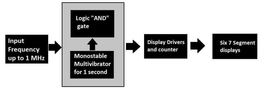
The proposed frequency counter circuit is based on the above architecture which is very simple and the circuit can measure up to 1 MHz frequency. The input frequency signal can be alternating current or DC pulses up to 12V peak.
A continuous input signal with an unknown frequency is fed to a block of circuit consisting of logic gates and a monostable multivibrator. This block will make sure that right amount of train of pulses are passed to the next stage of the circuit.
The next stage is display driver and counter, both the functionalities are embedded in to one and this stage is responsible for driving the 7 segment displays and also increments the count on the display as per the input signal from previous stage.
Working principle of the proposed frequency counter circuit:
Frequency is defined as number of oscillations per second (measured in hearts); to measure the frequency of a signal we just need to count the number of oscillations that occurred in one second time frame.
In the block diagram, we have a block dedicated for counting which counts the number of pulses that you input for measuring; now we need to stop the input signal at the counter section as we reach precisely one second.
To do this we are utilizing a timer which is tuned to output HIGH signal for 1 second and after the one second the input measuring signal gets cut-off to the counter section and the display will freeze. Now we will read the number of oscillations occurred in one second on the display and that’s your measured reading.
Now let’s try to implement the above working principle.
Circuit diagram:
The circuit diagram for the proposed frequency counter is segregated in to three parts for the purpose understanding them better.
Display and counter section:
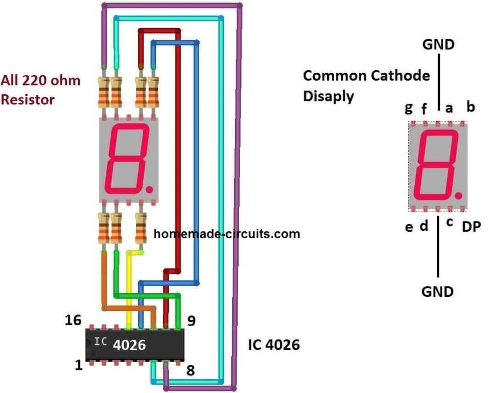
The display and counter section is responsible for driving the common cathode 7 segment display correctly and to count the signal and increment the number on the display.
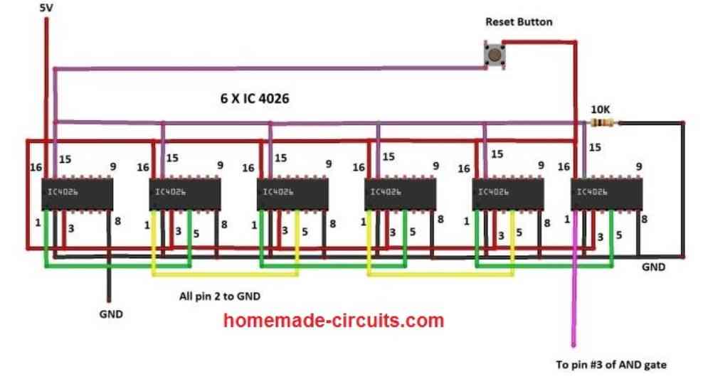
The above diagram shows how the 4026 ICs can be cascaded for measuring or counting frequency over a 6 digit display, each display being connected with each IC 4026. Each IC 4026 supports a single common cathode 7 segment display, and thus a total of six 7-segments displays can be connected with the above shown circuit.
The following image gives a magnified and elaborate details regarding how each 7-segment display module can be configured with each of the 4026 ICs in the above figure.
The above circuit consists of six IC 4026s which takes care of counting and displaying, one push button is provided to reset the count on the display to zero and one 10K pull down resistor is used. To understand how exactly the above circuit works we need to understand the pin description of the IC 4026.
Pin diagram of IC 4026:
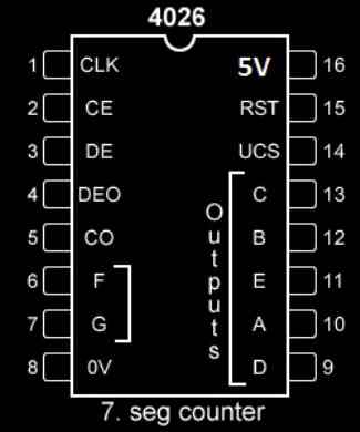
- Pin 1: Clock input. For every one clock pulse the display will increment by 1 digit.
- Pin 2: Clock Enable, this pin will be grounded during normal operation. If we connect this pin to Vcc, clock pulse at pin 1 will be ignored and no increment of count on the display.
- Pin 3: Display enable, when this pin is connected to Vcc, the 7 segment display will light up to show digits. If this pin is connected to ground, the display will not light up, but the count gets incremented in the background.
- Pin 4: Not used.
- Pin 5: Carry out, this pin gets high for every 10 input pulses. This pin is used for cascading multiple IC 4026 so that we can utilize two or more 7 segment displays. Pin 5 will be connected to pin 1 of another IC 4026.
- Pin numbers: 6, 7, 9, 10, 11, 12 and 13 are outputs for 7 segment display.
- Pin 8: Ground.
- Pin 15: Reset, by applying Vcc to this pin, it will reset the count to 0, during normal operation this pin is tied to ground.
- Pin 16: is Vcc.
Now let’s come back to the circuit. The IC 4026s are cascaded to 5 stages so that we can get a maximum reading up to 999999 or 1 million (minus 1), hence we can measure frequencies up to 1 MHz.
The right most IC receives the frequency signal to be measured, the right most IC will count up to 9 and when 10th pulse arrives, the count on its respective 7 segment display turns “0” and the very next IC 4026 at left hand side turns 1, this is because the IC’s carryout pin 5 is connected to clock pin 1 of the IC present at the left hand side. By connecting all other ICs in this fashion we will get a counter circuit that can count up to 999999.
A reset button is provided to reset the count of all 7 segment displays to “000000” when needed. A 10K pull-down resistor pulls the reset pin 15 to ground during normal use and when the reset button is pressed Vcc gets applied on pin 15.
Frequency sampling circuit:
The sampling circuit is responsible for sending the correct number of pulses to the counter stage. This circuit will chop the continuous signal that you are applying at the input to one second worth of signal samples.
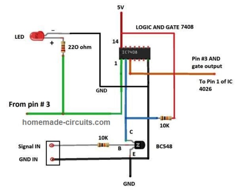
The output of AND gate IC 7408 (pin 3) is connected to display counter stage and the above illustrated (first circuit) has two inputs, one from the measuring input and one from monostable multivibrator (2nd circuit).
The signal is applied to the base terminal of the transistor and the output of the transistor (collector) is connected to the one of the input of logic AND gate. The purpose of the transistor is to provide high input impedance (resistance) to reduce loading effect on the input signal and also we can apply a much higher voltage at input (recommended maximum is 12V).
Since the transistor can only make its output go LOW, we need to connect a pull-up resistor to the collector pin, so that the input to AND gate can be both HIGH and LOW.
In case if you are applying alternating current signal, polarity can be ignored, in case of DC pulsating signal make sure that ground of input circuit is connected to ground of measuring circuit.
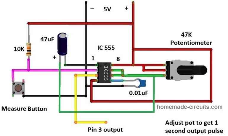
The monostable multivibrator is responsible for delivering 1 second HIGH signal to the other input terminal of AND gate. By doing so the measuring input frequency signal pass to the counter circuit only for 1 second (as per the definition of frequency) thus the unknown frequency gets displayed.
The monostable multivibrator is built using IC 555 and few passive components to set its output duration. A 47K preset or potentiometer is provided so that the user can calibrate the output duration to exactly 1 second.
When you press the measure button the IC 555’s pin 3 outputs a high signal for 1 second (assuming you set for one second) after that the output at pin 3 will stay low until you push it next time. When you press the “measure button” a LED lights up to indicate that the frequency is getting sampled.
Calibration of frequency counter:
The user needs to calibrate the circuit properly only then you can get a correct reading for an unknown frequency.
- With fully completed setup turn it ON; apply an input reference frequency of 1 KHz from a function generator. In case you don’t have a function generator use a 0-6V step down transformer and apply the AC 6V at the input, now you need to assume 50 Hz as its reference frequency.
- Press measure button, now you will get some random frequency measurement on the display. Now press reset button to bring the count to “000000”.
- Adjust the provided pre-set resistor / POT and retake the measurement until the display shows the reference frequency value that is 50 Hz or 1000 Hz.
- The accuracy of measuring unknown frequency will be only as good as the calibration.
- When you bring the readings on the display close to the reference value, your machine is ready to measure unknown frequencies.
The first frequency counter circuit concept discussed above involved the IC 4026 for the intended frequency measurements over 7 segment common cathode displays.
Now I have explained a couple of more circuits using IC 74LS47 and IC 4033 and see how these ICs can be configured into specific frequency counter designs, as I have explained below.
2) Frequency Counter Using IC 74LS47
The second frequency counter diagram shown below can be understood with the following points:
You may also want to Read: 5 Digit Frequency Meter Circuit
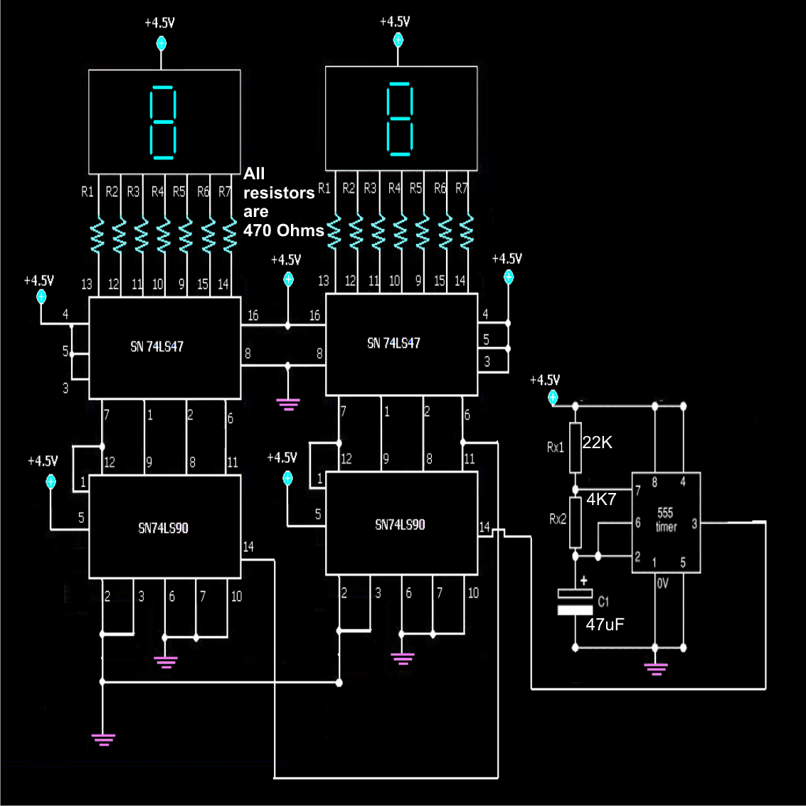
1. The IC 555 is configured in an astable mutivibrator mode (AMV).
2. AMV is a configuration in which the IC555 generates alternate high and low pulses at its pin number 3.
3. These pulses are simply the generation of positive voltages in succession at a certain rate; say for example 20 positive and negative alternate voltage peaks in one minute. The capacitor and resistor values can be adjusted for adjusting the generated pulse rate.
4. In the circuit the 74LS90and 74LS47 are used for counting the above pulses from the IC555.
5. The IC74LS90 accepts the pulses from the IC555 at its input pin no.14.
6. Its internal circuit converts these pulses in the form of special codes (binary) and fed in a certain sequence to the decoder IC 74LS47 through its output pin no.12,9,8,11.
7. The above codes are accepted by the decoder IC 74LS47 at its input pin nos.7,1,2,6 in the same above sequence.
8. The IC74LS47 now decodes this binary information and illuminates the LED display bars in such a way that it starts displaying the numbers 1 to 9 in response to the pulses generated by the IC555, meaning, the first pulse from the IC555 displays a no.1 over the right hand side display, the next pulse makes it display the number 2, then 3 and so on until the display reaches the number 9.
9. During the above procedure the left hand side display continues to show the number zero.
10. However the moment the right hand side display reaches the number 9, the next pulse overflows from pin 11 of the right IC74LS90 and becomes available to pin 14 of the left IC 74LS90 which now repeats the above procedure.
11. So now the left hand side begins continuing the counting by displaying the numbers 1 to 9 and we witness the ongoing counting with the displays modules together showing the number 11 until the number 99.
12. That's the maximum number of digits the shown counter design can display at the maximum.
13. For making the counter a three digit counter or a four digit counter, simply the above stages may be added in the same pin out sequence as the two modules are connected in the given diagram.
14. The input at the pin 14 of the first module can be replaced with any type of pulse that needs to be monitored or which needs to be counted.
The pins of the ICs which are connected to the positive and the negative points of the power supply are the supply input pins of the respective ICs which require precisely 5 volts for operating.
The resistors R1 to R7 on each display are connected for limiting current to the display LEDs so that a constant illumination is maintained and also for safeguarding the display LEDs from getting damaged.
3) Frequency Counter Circuit Using a Single IC 4033
The third circuit concept shown below can be also used for measuring or counting frequency or Hz. The IC is very simple to make and utilizes just a single IC 4033 and a common cathode display as the main ingredients.
Introduction
If higher frequencies in the the order of two or three digits are required to be measured, then simple the number of modules can be connected in series as described.The simple frequency counter circuit shown below will effectively convert any pulse at its input into a display over the 7- segment cathode block.The IC has an internal BCd to 7 segment translator which directly converts the pulses at its input to readable numerical bars at the connected display block.
Circuit Operation
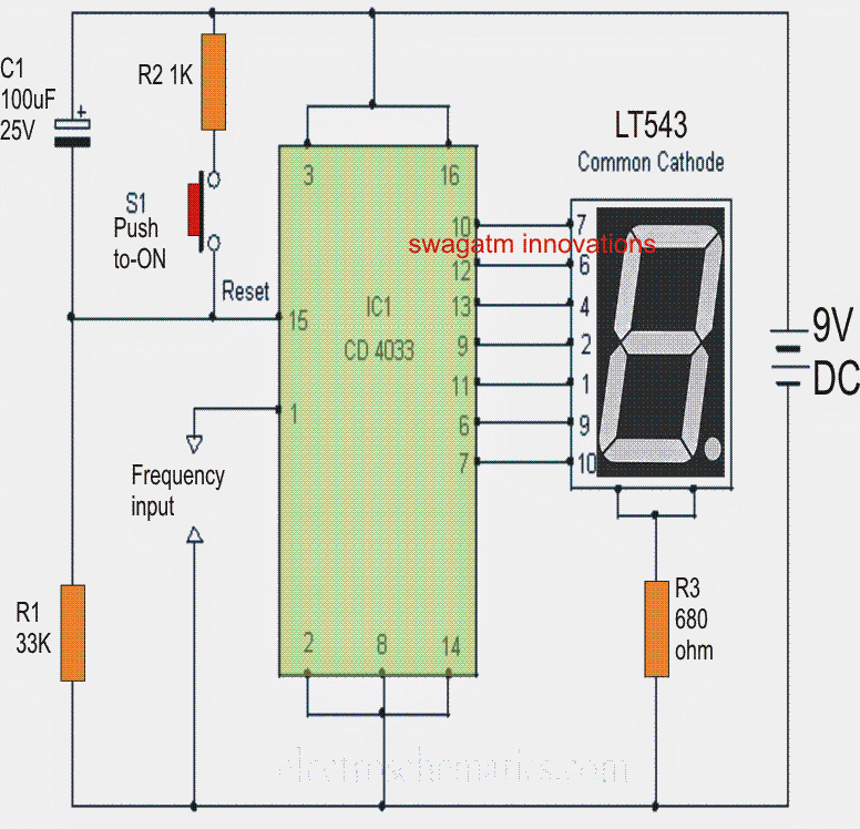
A single IC 4033 is able to handle only one common cathode display block and therefore the shown circuit is able to show numbers from 0 to 9 in response to the relevant clocks applied at its input.
The IC may be easily reset at any point. For example suppose 6 clocks were applied at the input and the the display now reads 6, it can be reverted to zero simply by pressing the shown push button, if needed.
Pin #1 is the input where the clock or the pulses are applied for counting.
In order to make the counter able to count to two digit or 3 digit or 4 digit etc. just include integrate the relevant number of modules as shown in the diagram and connect their outputs in the following manner:
Connect pin #5 of the first module to the clock input of the next module and connect pin #5 of the second module to clock input of the third module and so on.
Make the reset pins common, so that a single push button can be used for resetting all the modules at once.
Supply terminals will also need to be made into common rails.
A capacitor of 0.1uF should be connected close to the supply rail for decoupling purpose.
Circuit Diagram


Comments
Hi sir,
I am doing a project on “Design a frequency counter using PCB that can identify and display the frequency of a given clock pulse on a 7-segment display. The frequency range of the input signal shall be 1-7 Hz.” I tried using the 3rd circuit, that is using IC 4033. How can we provide a frequency input to the circuit. Also we tried to simulating it using proteus, but nothing worked. Can you please tell us what to do?
Hi Rishitha, The 4033 frequency counter circuit is correct and should work if it is built practically on a general purpose PCB. Please check your IC or the connections. Here’s another version of the 4033 frequency counter:
https://www.homemade-circuits.com/wp-content/uploads/2025/04/4033-frequency-counter.jpg
Sir this circuit was helpful
But what exactly happing is, in this circuit since we are using a mod 10 decade counter when we are supplying a input frequency of 1 Hz the 7 segment display is showing the count from 0 to 9 and then going back to 0, this loop is continuously occurring. And when we increase the frequency it’s counting fast.
But, what we need is, when we give a input of 4 Hz the 7 segment display should display the number 4. And the number on 7 segment display should match with our input frequency provided in between 1-7 Hz. We are using a frequency generator for the input.
Sir can you please suggest a circuit which will match the above requirement
Hello Rishita,
For that you will need a frequency meter circuit. Currently I don’t have a circuit using ICs, I have one using Arduino, as shown in the following link:
https://www.homemade-circuits.com/frequency-meter-circuit-using-arduino/
i am making this project with my classmates as my semester dld project and i had a few questions i was meaning to ask i am making the circuit with 47LS90 IC
1. i need to add 2 more displays to this circuit and according to what I understood i believe i need to connect pin 14 of the new counter ic the in this case the one of the left to pin 11 of the previous counter in this case on the right-side rest of the circuit is similar.
that’s what I’ve understood please do let me know if i am correct.
2. what the decoders connection to the display as i see no pin numbers at the display side.
To add two more displays you just have to replicate the connections which are done for the 4 ICs from the left, in the following diagram:
https://www.homemade-circuits.com/wp-content/uploads/2022/05/counter-using-4026-IC.jpg
The display’s a,b,c,d,e,f,g pins are shown in the diagram, so you can identify the pin numbers from these designations.
Please let me know if you have any further questions.
I want to make the counter using the ic4026, but would also like to increase the range into the VHF bands (up to 200 MHz).
Is there an ic that will do this? Or, do I have to make a separate counter? If so, is there one that would use the same component values?
I think it may be possible to measure a 200 MHz range or any other higher range using the above circuit, simply by dividing the frequency initially by 10, 100, 1000 etc using cascaded 4017 ICs. The divided output can be then fed to the above explained 4026 frequency counter circuit.
i have a turbine flow meter with mag pick up trying to read Gallon per minute here are specs:
30 milivolt peak sine wave output i have 3 gallons to 30 gallons 3100 pulses per gallon per minute
Hello
I m a novice in electronics but can follow simple to medium circuit diagrams, I have a load of led numeric module, and was looking to make a counter from 1Hz to 2Ghz, but cannot find any thing in the DIY zone, is this because of expense or difficulty. I’m a radio astronomer, building my own scope studying these frequency ranges
Hi, 2 GHZ is too high to measure using ordinary frequency counters like the ones explained above. Unfortunately I do not have a digital circuit that measure frequencies upto 2 GHz.
If input frequency will be 30 hz then it will count 30 in 1 second so after another 1 second will it change to 60 ? Then is possible to count frequency ?
that’s correct. Actually it is a pulse counter circuit.
I have a beehive and would like to count bees entering and bees exiting the hive.
This way I can determine how many bees return to the hive daily and keep track of the health of the hive.
My electronics knowledge is minimal.
Any response is appreciated.
John
It is very difficult to count the entry and exit, both ways for something as random as bees, I do not have this circuit at the moment.
I need a frequency meter circuit design using proteus for my uni project can anyone help? Thanks regardless
remove the 555 IC and replace it with your circuit whose frequency needs to be measured…..and connect its output with pin#14 of the counter IC