In this post I have investigated 4 simple 220V Mains Uninterruptible power supply (UPS) designs using 12V battery, which can be understood and constructed by any new enthusiast. These circuits can be used for operating an appropriately selected appliance or load, let's explore the circuits.
Design#1: Simple UPS using a Single IC
A simple idea presented here can be built at home using most ordinary components to produce reasonable outputs. It may be used to power not only the usual electrical appliances but also sophisticated gadgets like computers. Its inverter circuit utilizes a modified sine wave design.
An uninterruptible power supply with elaborate features may not be critically required for the operation of even the sophisticated gadgets. A compromised design of an UPS system presented here may well suffice the needs. It also includes a built-in universal smart battery charger.
Difference Between UPS and an Inverter
What’s the difference between an uninterruptible power supply (UPS) and an inverter? Well, broadly speaking both are intended to perform the fundamental function of converting battery voltage to AC which may be used to operate the various electrical gadgets in the absence of our domestic AC power.
However, in most cases an inverter may not be equipped with many automatic changeover functions and safety measures normally associated with an UPS.
Moreover, inverters mostly don’t carry a built in battery charger whereas all UPSs have a built in automatic battery charger with them to facilitate instant charging of the concerned battery when mains AC is present and revert the battery power in inverter mode the moment input power fails.
Also UPSs are all designed to produce an AC having a sine waveform or at least a modified square wave resembling quite like its sine wave counterpart. This perhaps becomes the most important feature with UPSs.
With so many features in hand, there’s no doubt these amazing devices ought to become expensive and therefore many of us in the middle class category are unable to lay their hands on them.
I have tried to make a UPS design though not comparable with the professional ones but once built, definitely will be able to replace mains failures quite reliably and also since the output is a modified square wave, is suitable for operating all sophisticated electronic gadgets, even computers.
All the designs here are offline type, you may also want to try this simple online UPS circuit
Understanding the circuit Design
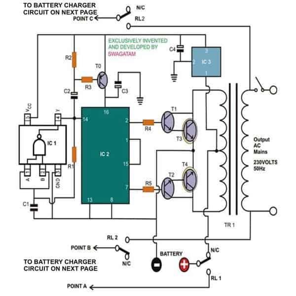
The figure alongside shows a simple modified square inverter design, which is easily understandable, yet incorporates crucial features.
The IC SN74LVC1G132 has a single NAND gate (Schmitt Trigger) encapsulated in a small package. It basically forms the heart of the oscillator stage and requires just a single capacitor and a resistor for the required oscillations. The value of these two passive components determines the frequency of the oscillator. Here it’s dimensioned to around 250 Hz.
The above frequency is applied to the next stage consisting of a single Johnson’s decade counter/divider IC 4017. The IC is configured so that its outputs produce and repeat a set of five sequential logic high outputs. Since the input Is a square wave the outputs are also generated as square waves.
Parts list for the UPS Inverter
R1=20K
R2,R3=1K
R4,R5 = 220 Ohms
C1=0.095Uf
C2,C3,C4=10UF/25V
T0 = BC557B
T1,T2=8050
T3,T4=BDY29
IC1= SN74LVC1G132 or a single gate from IC4093
IC2=4017
IC3=7805
TRANSFORMER=12-0-12V/10AMP/230V
Battery Charger Section
The base leads of two sets of Darlington paired high gain, hi-power transistors are configured to the IC such that it receives and conducts to the alternate outputs.
The transistors conduct (in tandem) in response to these switching and a corresponding high current alternating potential is pulled through the two halves of the connected transformer windings.
Since the base voltages to the transistors from the IC are skipped alternately, the resultant square impulse from the transformer carries only half the average value compared to the other ordinary inverters. This dimensioned RMS average value of the generated square waves very much resembles the average value of the mains AC that is normally available at our home power sockets and thus becomes suitable and favorable to most sophisticated electronic gadgets.
The present uninterruptible power supply design is fully automatic and will revert to the inverter mode the moment input power fails. This is done through a couple of relays RL1 and RL2; RL2 has a dual set of contacts for reversing both the output lines.
As explained above an UPS should also incorporate a built-in universal smart battery charger which also should be voltage and current controlled.
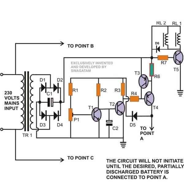
The next figure which is an integral part of the system shows a smart little automatic battery charger circuit. The circuit is not only voltage controlled but is also includes an over current protection configuration.
Transistor T1 and T2 basically form an accurate voltage sensor and never allows the charging voltage upper limit to exceed the set limit. This limit is fixed by setting the preset P1 appropriately.
Transistor T3 and T4 together keep an “eye” over the rising current intake by the battery and never allows it to reach levels which may be considered dangerous to battery life. In case the current starts drifting beyond the set level, the voltage across R6 crosses over – 0.6 volts, enough to trigger T3, which in turn chokes the base voltage of T4, thus restricting any further rise in the drawn current. The value of R6 may be found using the formula:
R = 0.6 / I, where I is the charging current rate.
Transistor T5 performs the function of a voltage monitor and switches (deactivates) the relays into action, the moment mains AC fails.
Parts list for the Charger
R1,R2,R3,R4,R7=1K
P1=4K7 PRESET, LINEAR
R6=SEE TEXT
T1,T2,=BC547
T3=8550
T4=TIP32C
T5=8050
RL1=12V/400 OHM, SPDT
RL2=12V/400 OHM, SPDT, D1—D4=1N5408
D5,D6=1N4007
TR1=0-12V, CURRENT 1/10 OF THE BATTERY AH
C1=2200UF/25V
C2 = 1uF/25V
Design#2: Single Transformer UPS for Inverter and Battery Charging
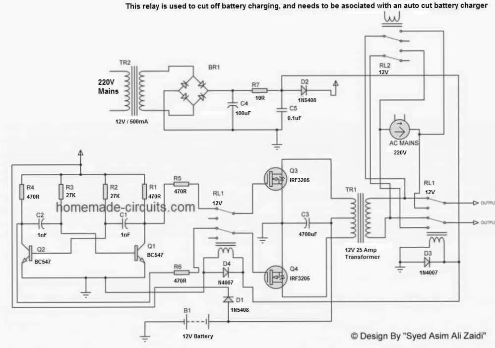
The next article details a simple transistor based UPS circuit with a built-in battery charger circuit, which can be used for getting an uninterruptible mains power output cheaply, in your homes and office, shops etc. The circuit can be upgraded to any desired higher wattage level. The idea was developed by Mr. Syed Xaidi.
The main advantage of this circuit is that it uses a single transformer for charging the battery as well as for operating the inverter. Meaning you don't have to incorporate a separate transformer for charging the battery in this circuit
The following data was provided by Mr. Syed through email:
I saw that people are getting educated by your post. So, i think you should explain people about this schematic.
This circuit has astable mutivibrator based on transistors as you did. The capacitors c1 and c2 are the 0.47 for getting output frequency about 51.xx Hz as i measured but it is not constant in all cases.
The MOSFET has reverse high power diode that is used to charge the battery there is no need to add a special diode to the circuit. I've shown the switching principle with relays in the schematic. RL3 must be used with a cutt off circuit.
This circuit is very simple and i've tested it already. I am going to test another design of mine will share with you as soon as test is done. It controls output voltage and stabilize that using PWM. Also in that design i am using transformer 140v winding for charging and BTA16 for controlling the charging amperes. Lets hope for the Good.
You're doing best. Never Quit, Have a wonderful day.
Design#3: IC 555 Based UPS Circuit
The 3rd design I have explained below is simple UPS circuit using PWM, and therfeore becomes perfectly safe for operating sophisticated electronic equipment like computers, music system etc.
The entire unit will cost you around $3. A built in charger is also included in the design for keeping the battery always in a topped up condition and in a stand by mode. Let’s study the whole concept and the circuit.
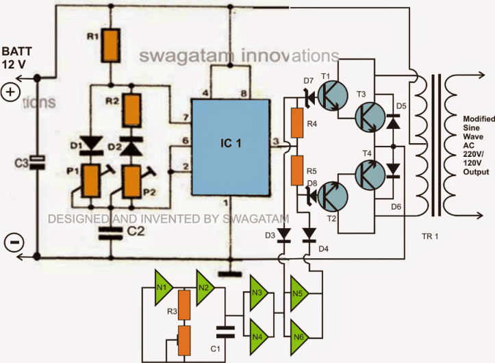
The circuit concept is quite basic, it’s all about making the output devices switch according to the applied well optimized PWM pulses, which in turn switches the transformer to generate an equivalent induced AC mains voltage having identical parameters to a standard AC Sine wave-form.
Circuit Operation:
The circuit diagram can be understood with the help of the following points:
The PWM circuit utilizes the very popular IC 555 for the required generation of the PWM pulses.
The presets P1 and P2 can be set precisely as required for feeding the output devices.
The output devices will respond exactly to the applied PWM pulses from the 555 circuit, therefore a carefull optimization of the presets should result in almost an ideal PWM ratio that can be considered quite equivalent to a standard AC waveform.
However since the above discussed pWM pulses are applied to the bases of the both the transistors positioned for switching two separate chennels would mean a total mess, as we will never want to switch both the windings of the transformer together.
Using NOT gates for Inducing the 50Hz Switching
Therefore another stage consisting a few NOT gates from the IC 4049 has been introduced, which ensures that the devices conduct or switch alternately and never all at a time.
The oscillator made from N1 and N2; execute perfect square wave pulses, which are further buffered by N3---N6. The diodes D3 and D4 also plays an important role by making the devices respond only to the negative pulses from the NOT gates.
These pulses switch OFF the devices alternately, allowing only one channel to conduct at any particular instant.
The preset associated with N1 and N2 is used to set the output AC frequency of the UPS. For 220 volts, it must be set at 50 Hz and for 120 volts, it must be set at 60 Hz.
Parts List for the UPS
R1, R2, R3 R4, R5 = 1K,
P1, P2 = as per formula,
P3 = 100K preset
D1, D2 = 1N4148,
D3, D4 = 1N4007,
D5, D6 = 1N5402,
D7, D8 = 3v zener diode
C1 = 1uF/ 25V
C2 = 10n,
C3 = 2200uF/25V
T1, T2 = TIP31C,
T3, T4 = BDY29
IC1 = 555,
N1…N6 = IC 4049, please consult the datasheet for the pin out numbers.
Transformer = 12-0-12V, 15 Amps
The Battery charger circuit:
If it’s an UPS, the inclusion of a battery charger circuit becomes imperative.
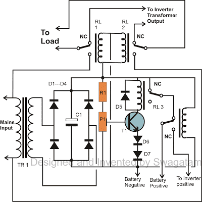
Keeping the low cost and simplicity of the design in mind, a very simple yet reasonably accurate battery charger design has been incorporated in this uninterruptible power supply circuit.
Looking at the figure we can simple witness how easy the configuration is.
You can get the entire explanation in this battery charger circuit article The two relays RL1 and RL2 are positioned to make the circuit completely automatic.When mains power is available, the relays energize and switch the AC mains directly to the load via there N/O contacts. In the meantime, the battery also gets charged through the charger circuit.The moment AC power fails, the relays revert and disconnect the mains line and replaces it with the inverter transformer so that now the inverter takes charge of supplying the mains voltage to the load, within milliseconds.
Another relay RL4 is introduced to flip its contacts during power failure, so that the battery which was kept in the charging mode is shifted to the inverter mode for the required generation of the back up AC power.
Parts List for the Charger
R1 = 1K,
P1 = 10K
T1 = BC547B,
C1 = 100uF/25V
D1---D4 = 1N5402
D5, 6, 7 = 1N4007,
All relays = 12 volt, 400 Ohm, SPDT
Transformer = 0-12V, 3 Amps
Design#4: 1kva UPS Design
The last design but by far the most powerful discusses a 1000 watt UPS circuit powered with a +/- 220V input, using 40 nos of 12V/4 AH batteries in series. The high voltage operation renders the system relatively less complex and transformerless. The idea was requested by Aquarius.
Technical Specifications
I am your fan & have built many projects for my personal use with success & had a lot of pleasure. God bless you. Now I intend to build a 1000 watt UPS with a different concept (inverter with high voltage input dc).
I will use a battery bank of 18 to 20 sealed batteries in series each 12 volts/ 7 Ah to give a 220+ volts storage as input to a transformerless inverter.
Can you suggest a simplest possible circuit for this concept which should include a battery charger + protection and auto switching by mains failure. Later I will include a solar power input too.
The Design
The proposed 1000 watt UPS circuit can be built by using the following two circuits where the first one is the inverter section with the required automatic changeover relays. The second design provides the automatic battery charger stage.
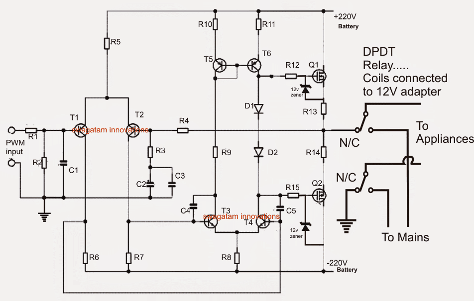
The first circuit which depicts the 1000 watt inverter consists of three basic stages.
T1, T2 along with the associated components form the input differential amplifier stage which amplifies the input PWM signals from a PWM generator which could be a sine generator.
R5 becomes the current source for providing optimal current to the differential stage and to the subsequent driver stage.
The section after the differential stage is the driver stage which effectively raises the amplified PWM from the differential stage to sufficient levels for triggering the subsequent power mosfet stage.
The mosfets are aligned in a push pull manner across the two 220V battery banks and therefore switch the voltages across their drain/source terminals to produce the required AC 220V output without incorporating a transformer.
The above output is terminated to the load via a relay changeover stage consisting of a 12V 10amp DPDT relay whose triggering input is derived from the utility mains via a 12V ac/DC adapter. This triggering voltage is applied to the coils of all the 12V relays that's used in the circuit for the intended mains to inverter changeover actions.
Parts List for the above 1000 watt UPS circuit
All resistor CFR 2 watt rated unless stated.
R1, R3,R10,R11,R8 = 4k7
R2,R4, R5= 68k
R6, R7 = 4k7
R9 = 10k
R13, R14 = 0.22 ohms 2 watt
R12,R15 = 1K, 5 watt
C1 = 470pF
C2 = 47uF/100V
C3 = 0.1uF/100V
C4, C5 = 100pF
D1, D2 = 1N4148
T1, T2 = BC556
T5, T6 = MJE350
T3, T4 = MJE340
Q1 = IRF840
Q2 = FQP3P50
relay = DPDT, 12V/10amp contacts, 400 ohm coil
Battery charger circuit for charging the 220V DC battery banks.
Although ideally the involved 12V batteries should be charged individually via a 14V supply, keeping simplicity into account a universal single 220V charger was finally found to be more desirable and easy to build.
As shown in the diagram below, since the required charging voltage is within the vicinity of 260V, the mains 220V output could be seen directly used for the purpose.
However applying the mains directly could be dangerous for the batteries due to the massive amount of current it involves, a simple solution using a 200 watt series bulb is included in the design.
The mains input is applied via a single 1N4007 diode and through a 200 watt incandescent bulb which passes through a switching relay contacts.
Initially the half wave rectified voltage is unable to reach the batteries due to the relay being in the switched OFF mode.
On pressing the PB1, the supply is momentarily allowed to reach the batteries.
This prompts a corresponding level of voltage to be generated across the 200 watt bulb and is sensed by the opto LED.
The opto instantly responds and triggers the accompanied relay which instantly activates and latches ON and sustains it even after PB1 is released.
The 200 watt bulb could be seen glowing slightly whose intensity would depend on the charged condition of the battery bank.
As the batteries begin charging, the voltage across the 200 watt bulb begins dropping until the relay is switched OFF as soon as the battery full charge level is reached. This could be adjusted by setting up the 4k7 preset.
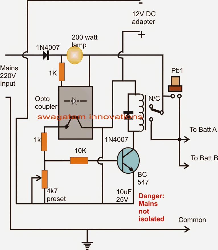
WARNING: The above circuit is not isolated from mains AC and therefore is extremely dangerous to touch in uncovered and switched ON condition. Extreme caution is advised while testing this circuit.
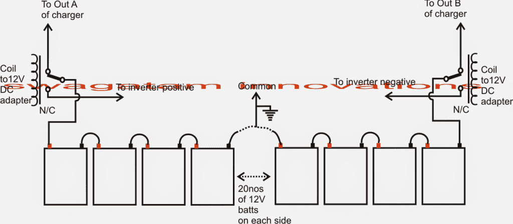
The output from the above charger is fed to the battery bank through a couple of SPDT relays as shown in the following diagram.
The relays make sure that the batteries are put into the charging mode as long as the mains input is available and is reverted to inverter mode when mains input fails.



Questions & Answers
IC3 is a voltage regulator IC for safeguarding the ICs against high voltage surges.
The battery positive is connected to primary center tap, this battery voltage should also go to IC3 input, so it's connected there.
everything is explained in the article, please read it.
use 2n3055 for T3,T4
6 amps will do.
use ic555 astable oscillator in place of SN74….
use a single Schmidt nand gate as found in IC4093
yes it can be used
upto 50 watts
use a 6amp fuse in series with battery positive.
12 amp transformer will also work here.
pls tell me the range of battery used here?
pls tell me the range of battery used here……
it'll be as per your requirement…
Sir if i am using 60 Ah battery and a 300 W tranaformer what will be the maximum discharge current flowing to the transformer secondary????
Will it affect the incorporating ICs and components badly if the discharging current goes much high??????
discharge rate will depend on how much load you connect at the o/p
SIR I THINK ALL THE PROBLEMS OCCURED TO ME WAS DUE TO THE SERIOUS 'shoot through problem' CAUSED BY ERRANEOUS SIGNAL FEDING OF THE GATES.OF THE MOSFETS( MAY BE AT THE SAME TIME ) that had occured due to the variation of duty cycle of the signal from 50/50. I think my calculations for R & C values in the oscillating stage of 4047 is wrong. I've used R=22.7 K adjusted by a linear 47K pot and C was selected to be 0.1 uf(104) in accordance with the formula f=1/(8.8RC) . But for this i had set f to 50 . So that was the mistake. Wasn't it??????
Sir let me ask one more doubt to u that even i am getting 50/50 duty cycle with approx. 50 Hz signal, will it undergoe any shoot through again????
Also can i use a MOVRD240/20 varistor at the secondary terminal in parallel with a 0.1uf/600 V and 2.2 uf/200V capacitors to avoid damage to the appliances from higher voltage
tip36 will not work in the above design.
single mosfets can be used in place of the two transistors on each channel.
Ram,a 4047 IC will never produce shoot throughs, it's internally protected from this.
select any standard 4047 circuit from any online source and select the components as per that circuit, instead of calculating it yourself.
MoV is not necessary in a 4047 circuit.
You can use 0.1uF and tweak the resistor value for getting the exact optimzation
…it should be 0.01uF not 0.1uF
Sir which is better for stable working at high output load an IRF540n or IRFZ4????
all mosfets are good, they only differ by their voltage and current specs, which must be selected appropriately.
Dear sir,
How can we calculate the maximum power that can be delivered by this circuit given the specifications of battery as well as transformer????'?
Any formula is there?
Dear Alex,
power will depend on the battery AH rating and the trafo wattage, the IC circuit will remain same for all the variations
Sir, i am not getting any ac output from this circuit. I have used IC CD4011 ( quad two input NAND GATES) instead of CD4093 also each transistor pairs at output were replaced by IRF540N mosfets .
0.095uf capacitor was accurately set up by paralling capacitors 0.047uf*2 and 0.001uf(102)
SIR PLEASE LET ME KNOW HOW TO ENSURE WHETHER IC4017 IS WORKING WITHOUT MEASURING SIGNAL FREQUENCY
Ram,you are doing as per your own wish and will,so I cannot suggest you anything.
you were worried about mosfets getting burnt with 4047 IC circuit so i suggested you to use transistors in your 4047 circuit by referring the above circuit.
Now you are making the above circuit with mosfets… inviting new problems.
Stick with your original 4047 circuit and use transistors at its output just as done for the above circuit.
In the above circuit 4011 will work but with two or three gates together.
4093 will allow only a single gate to be used
f = 1/0.8RC
4011 will work but with two or three gates together.
4093 will allow only a single gate to be used
I Am Very sorry for disturbing you again SIr.
Actually i was in the middle of searching for a better 200 W to 250W inverter which is suitable to operate even sophisticated components. Atlast i found it in this article. Now i am not so affraid of getting the MOSFETS blown, since it is working properly when i checked the whole in last night producing a favourable ac output. SO I decided to stick on this new project since it can fullfill my needs and used the components as available with me( just changed IC4093 and output stages as said before).. I must must have to implement this to suit my needs. So expect your valuable suggestions for this. Now i want to know , how the gates in 4011 can be used to produce the same result as that of 4093 and make the entire one in working condition
Sir i have connected three NAND GATES in 4011 in series. ( output of first NAND gate connected to one of the inputs of second NAND gate and there inputs shorted. Its output further connected to the shorted input terminals of the 3rd one. Finally 0.095 uf connected b/w the shorted inputs of 1st gate and ground only. Also the 20 k resistance connected in between the first input terminals and the output of the last NAND GATE). When the testing has completed the result was fruitfull. I got ac out. But a small problem is there that i am getting only about 120v out. I could work a 3V adapter for torch with it nut not a table fan. Will you plz help me???
OK, if you have succeeded with it then it's a great news.
since it's a modified sine wave inverter it'll produce 50% less output if the batery/trafo voltages are rated identically.
for a 12-0-12V trafo you will need a 24V battery for getting 220V with this circuit. you can connect 2nos 12V bats in series for getting 24V.
..but be sure to give 12V only to the ICs…..you can do this by extracting 12V separately from one of the 12V batts.
use a 4093 instead.
what much maximum power can be drawned from a 24V 20Ah combination SIR????
Will i get more power by adding an additional 12 V 20Ah battery???? how????
around 200 watts..yes more bats can be added for increasing power.
Hellow sir……….. is this circut features an automatic load correction??? i mean will i get constant 230 V even various loads are used at the load side utilizing differrent loading voltages???
If it is not, how can it be made to operate such a feature???
No this circuit does not have this feature, it will require an external circuit for implementing it…I'll try to discuss it in a new post soon.
Sir i want your help again. I think your suggestion at this time is very necessary to complete my work.
I have done everything as per you suggestions. Put 24V instead of 12 and extract ed separate 12v for ICs from one of the batteries( 12V fed to the ICs after regulation using 7805 ). now i got better ac out which could be understood by a more brighter light indication by TESTER( my voltmeter shows only 23.5 when the range is put in 750V ac. But the led of tester becomes more brighter than the last time at which it was less bright and showed 120V in voltmeter ). But the real problem is , i can't operate a fan 6A rated by this provided all the batteries are fully charged
Will it be an error due to mismatch of value of feedback resistance R1(20k) ???
Can a pot be used there and adjusted at run time untill fan rotates????
yes you can use 100k pot in series with the 20k pot and adjust it for getting 50Hz.
LED tester is useless for testing an inverter, you should use a 100watt bulb at the output of the transformer.
check battery power by connecting a car headlight bulb to it…if the bulb lights up very brightly with voltage of the batt not dropping below 12.5v, would confirm a fully charged battery.
Hai sir, Ram again.
As per your suggestion i used 24 V battery bank for the purpose of 230V generation. Now i need a charger suitable for the battery. SO i have created a logic turn over switch for the battery bank which allows the batteries to connect in series when power is needed during power failure and connect in parallel when charging mode is reached. I have drawn a simple schematics to make it practical using only a rated relay. I have posted the diagram in the link given below. Please study it and point out mistakes if any sir.
postimg.org/image/6zzajm78j
May i ask you onething that ,can the 24V battery be charged with a 15-0-15 transformer by extracting 30V from the terminal leads????
i have made such a schematic intented to modify for parallel charging of higher rated batteries which are usually connected in serious under load…n
Sir, the image i posted before is little blurred. Here is a better version. Plz check it ou
postimg.org/image/s6j9wxexh/
Hi Ram,
It looks correct to me, however will need practical verification for confirmation.
yes 30V from 15-0-15 can be used for charging a 24V baterry
20k is not the correct value.
and C will be in farads not in uF, so you should first convert uF into F before substituting the values in the formula.
Sir what are the values of frequencies coming from pin2 and pin7 of IC4017 in this figure??? Can i use these values to make an assumption to ensure that the exact 50Hz ac is coming out of transformer primary????
Superman, it should be 50Hz on either pins, yes surely if this is confirmed, the output from the trafo would be also confirmed with the same.
Sir,
Can you please suggest a PWM based inverter circuit that uses the PWM chip ic SG3524 as the heart of entire operation ??
The output of the inverter shouldn't be fluctuated with varying loads and the inverter should be capable of operating atleast a 250 W load.
One of the most necessary requirement that i missed to say is that, this inverter should be capable of driving even sophisticated components such as laptops
Arun, you can try the following circuit, it can be used for operating laptops also:
https://www.homemade-circuits.com/2013/01/modified-sine-wave-inverter-circuit.html
sir, are the two circuits above working? are they well-tested?
yes. tested and working.
can i use 6amps instead of 10amps transformer? will it affect the circuit?
you can use 6 amps, it will work
great! thanks! but what appliances this ups can possibly drive if i use 6amps transformer?
appliances such as lights fans below 60 watts can be operated with a 6amp trafo
thank you Swagatam for that info. I just have few more questions about this project:
1. what is the replacement for SN74LVC1G132?
2. did you simulate the circuit on breadboard or in proteus?
3. what is the power rating of the resistors?
4. do you have a pcb layout on this?
5. is this project uses pulse width modulation?
1)you can use a single nand gate from the IC 4093 or a 555 IC astable will also work.
2)I simulated it in my mind not with any any software.
3)all resistors are 1/4 watt except R6
4) it's a crude modified sine wave, but does not incorporate a pwm circuit.
thank you sir! do you have any simple circuit that uses digital communication?
sorry, presently i do not have this circuit.
it's ok sir.
if i use 6 amp transformer, how may hours can it operate an appliance below 60 watts?
the backup time will depend on the battery AH rating, higher value will produce higher backups and vice versa….. it has no connection with transformer ampere rating.
thank you sir! can an IC be added in the above circuit to save standby power? and what IC should be used?
no that cannot be done, simply disconnect the battery and it will stop the circuit from any consumption.
Hey…your design is great.I wanted to know how you calculated the capacitor and resistor values to get a frequency of 250Hz.and how can i change the values to get a 50Hz frequency?
Thanks Robe,
Actually it has to be 250Hz at pin14 of the IC for achieving 50Hz across the transistor bases, since the sequencing of the output pins of 4017 are not continuous rather skipped in between for getting the proposed modified output.
Sir,
How much power will i get from my 24 V 40 Ah battery bank and a 230/11.5-0-11.5V power transformer ?????
Battery bank formed by the series combination of two 12 V 40 Ah battery banks, each 12V 40 Ah battery bank is a parallel configuration of two 12V 20 Ah sealed lead accid batteries, means i have formed a 24 V 40 Ah battery bank with suitable configurations of four 12V 20 Ah batteries.
Transformer has 5 input windings and 4 output windings. The maximum voltage at secondary terminal is 15 V
You can easily obtain 250 watts from 24V/40ah provided the trafo is also rated at around 300 watts…..
Sir can you please suggest a method by which the ouput voltage of the above circuit willn't further deviate with varying loads ????
Arun, you can try incorporating the following circuit with the above circuit:
https://www.homemade-circuits.com/2014/01/automatic-output-voltage-regulator.html
sir, is there any replacement for bc547 BC557B, 1n5408, TIP122 and TIP32C?
TIP122 does not have an easy alternative….for the rest can be found in the link I provided you in your other comment
sir im confused about relay 2? the contact in point b and c are in NC only?
RL2 is a DPDT relay which has two sets of contacts inside one package.
oh i see..so its DPDT in relay 2..can i use another relay and put at relay 2 parallel in the circuit ?..because i can't find in my place a DPDT relay.
yes, that's correct, and you can surely use two SPDT relays and join their coils in parallel for getting the same results.
sir is there any replacement or alternative that i gave in the above comment, the electronic components?because i have same problem in DPDT relay..i really appreciate all your works and very nice masterpiece..thank you for this.
Please refer to the link which I gave in your other comment….it consists of the list of the all the equivalents…
TIP122 has no direct replacement
sir, i need you help..i made the ckt. above..and im having a problem in the circuit in the UPS..in the the inverter ckt. the output voltage in the transformer is only 150v instead of 230v..why?..please help me sir
Erns, please use a 9-0-9v or a 6-0-6V trafo, this will solve the issue
hi sir we have to make a 100watt ups. so sir in second circuit the value of resistance R6 is in ohm or kiloohm.
Hi Milan,
It's in Ohms.
Hello sir
In ups 100watt bulb does not glow when main switch is off.Any solutions for this…Sir
When main switxh is off outputvoltage is reduce…
you should first make the inverter section separately and confirm the results and then integrate with the changeover relays.
Sir what is the rating of battery and step up transformer .we have to make 100 watt ups….
9-0-9V/10amp/220V is the transformer rating
the battery could be a 12V 25AH lead acid battery.
transformer should be a 6-0-6v/10amp..it's clearly mentioned in the parts list
Sir what is the output of this ups circuit?????????
220v ac
Hi mr.Swagatam,
I am Jayasuriya from Sri Lanka.While appriciating your valued replies,Kindly explain how to measure power output(wattage) of a locally made power inverter
Hi Hapu,
thanks!
the easiest way to test it is by loading the output of the inverter gradually until the voltage begins dropping. The total value of the load wattage during that instant will provide the wattage capacity of the inverter.
Sir, it z very interesting to implement your ideas…. Thank you so much sir for providing us such various ideas.
Now i am in the middle of making a small 150 W UPS system …. I have a 15 V 5A Old Thoshiba laptop charger, four no.s of 12 V 20Ah sealed lead accid batteries taken from an old electric scooter, and some necessary components to make out the UPS……
The main intention behind this is : i want to charge my mobile phone, laptop, even a torch during power failure.. The inverter should also support a table fan….so a maximum rating of 150 W is necessary….
Since i want to operate such sophisticated components , could u plz suggest me the most appropriate version satisfying all ma needs..n
Also i want to know that, if the UPS is based on PWM, what battery voltage to be selected…12 or 24 ??…
I have only a 15 V charger with me… So if i have to use 24 V confih. (series combination of two parallel configuurations each 12V 20 Ah batteriea = 24 V 40 Ah ), how it be possible to break all these config. and forming a complete parallel config. ( 12 V 60 Ah ) for charging7 ????
Thanks Arun!
Here fan is the only gadget that will require 220V rest of the items (cell phone, laptop, torch) can be actually charged directly from the battery, so an inverter won't be necessary for those items.
anyway if you want to charge them from the same inverter you may do so and it won't be necessary to employ a sine wave inverter since all these items work on DC and any AC whatsoever will be ultimately converted to DC, so even a square wave inverter would work for the application.
you can try the desin that's shown in the above article or you can try the one that's shown in the following link
https://www.homemade-circuits.com/2012/09/mini-50-watt-mosfet-inverter-circuit.html
both can handle upto 200 watts
for charging a 12V 20ah battery you would require a 14V/3amp battery, so your smps will need to be 14V at least, 12V will not work.
Sir what much wattage to be expected by two 12V 20Ah batteries in series ?…. The Transformer is rated at 12V,300W
sir i failed in executing the below design for my need
https://www.homemade-circuits.com/2012/09/make-400-watt-mosfet-sine-wave-inverter.html#comment-form
Again i have decided to go on with the current UPS design…. Now as a whole saying i got AC out…. But a 100 W bulb didn't give a single glow on connecting it at the output of the transformer… On measuring the amount of current passing to the centre secondary winding of the inverter transformer , i came to know that only 0.77A current is flowing, thereby it seemed to produce a power of only 18.48 W ( 24.5 * 0.77 ) at the output.. That is why the bulb didn't glow…
SO Tell me sir, how the amount of current ( that to be drawn from the battery ) could be increased to a minimum level of 7A, so that inverter output reaches a minimum of 175W….
NOTE:::: SIR, I HAVE TESTED THE BATTERIES USING A CAR HEADLIGHT LAMP ( 12V, 60 W )……. THE AMMETER SHOWED A READING OF ABOUT 5A AT FULLY CHARGED CONDITION OF THE BATTERY.
I have used 2 no.s of 20Ah batteries in series……
Eventhough the expected wattage couldn't be achieved by this config., the current drawn from the 40 Ah config ( Series config. of two battery banks, each banks are the parallel config. of separate batteries ) was also seen to be so low, so that the 100 W bulb couldn't start glowing…
YOUR HELP IS THE ONE AND ONLY EXPECTED SOLUTION AT THIS POINT
Arun, What is the rating of the transformer that you have used? If it's a 5amp transformer it should weigh about 4 to 5kgs, if it's much lighter than this would indicate a lower rated transformer which won't produce the intended results.
the voltage rating of the trafo must be lower than the battery voltage, for 24V it must be 18-0-18V
check the gate voltages, the peak voltage should be 12V since it's supply is 12V and the average voltage should be 6V since it's operating at 50% duty cycle.
please check all this and correct them accordingly.
12-0-12V will also do, 300watt must weight at least 12kgs.
initially keep the PWM diodes disconnected and check the results.
Sir, another doubt too
Can i really use sophisticated equipments such as laptops, mobile phone chager etc. with this UPS circuit ??
yes, it will support all those gadgets.
i CAN'T SEE ANY PWM DIODES IN THIS CIRCUIT SIR…….
i have send you mail… could you plz check it SIR
I was referring to the previous 400 watt design, I was trying to troubleshoot that circuit.
Sir,
Will the voltage be stable at the output…
I mean,, will there be any problem in connecting more than one instruments at the output.
I want to connect maximum of 4 instruments ( A Notebook charger of 13.5 W, A mobile charger of 5W, A Table fan of 80 W, )
Will they get burned ???
And if this connection is not possible, how to make the AC Voltage stable independent of different loads in this circuit???
Arun according to me there won't be any problem with the mentioned gadgets since all these employ SMPS regulated power supplies except the fan which is not so vulnerable anyway..
To make things stable the PWM feature is essential.
By the way how did you proceed with the above circuit, what components did you use?
Please send me the built units picture for reference.
I have also an another doubt sir…
1). What is the main difference between a normal MOSFET inverter and an H bridge MOSFET Inverte ?
2). Will the former one have more efficiency than the other
3). Does the H bridge means the config. in which 4 MOSFETS are used with each pair of mosfets connected in parallel ??
H bridge will require a transformer with no center tap which allows the use of smaller trafos and thus efficiency increases.
H-bridge can be made using sophisticated driver ICs which are specifically designed for such applications thus faults could be rare with this topology.
you may refer to one good design here:
easy-electronic-circuits.blogspot.in/2014/05/100-watt-to-1000-watt-pure-sinewave.html