In this post I have explained a DTM based FM remote control circuit which can be used for controlling 4 individual appliances remotely by pressing four corresponding buttons on the DTMF transmitter handset. The idea was requested by Mr. Sunaabh Sarkar.
Technical Specifications
I came across your blog "Homemade The Designs Just for You" quite by chance as I was googling for some circuit and quite frankly I am indeed very impressed by your inputs.
I am an architect by profession but when it comes to hobby Its photography after my first choice.. electronics. As a child some 4 decades ago, I used to be fascinated watching my fellow seniors from the Naval NCC class build ships in our electronics lab.
The passion has remained in the heart and now when I was forced to take a 'retired back seat' from my active profession due to some unavoidable circumstances, I thought the time to be right to pursue what I had always wanted to do in my heart. Build working model of Ships... well just for the fun.
I started with the old worn out RC toys my kids used to play with by "reverse engineering them" to my benefit while building the 5 vessels (all out of household wastes like old ball pens, remote control covers, discarded flexible conduit pipes, plastic bottles and things like those),
I have so far built. When there were no more old RC toys around, I would go and buy some new cheap ones and used the electronics to power my models.
New or old, the commercially available RC units came with their limitations (like range or performance).
The professional ones other modellers use come with their own hitches and which if not for their exorbitant prices, they have remained unavailable for one reason or the other.
I wish I had a chance to study electronics as a subject of my higher education, so that I could be designing electronic circuits rather than designing houses ;).
However, I had this idea lingering on for quite some time, though I confess its not unique or new... controlling devices using DTMF codes. Ever since Cellphones have taken the front seats, push button land line phones have become vogue and I had been contemplating powering up one of them to generate DTMF codes... then feeding these codes to an audio transmitter in the FM range.
The signal transmitted can be received by a FM receiver. The DTMF tones transmitted can then be decoded by a decoding circuit to trigger at least 6 individual circuits driving toy motors. But the moron that I am, I' can only dream.
Googling does me little help. There are some circuits available on line, but they require programming too... well at my age I guess by the time I get to know how to write a program and make use of one, there will be little left of my dwindling eyesight to build my dream ship.
I was wondering if you could kindly help me by designing/ suggesting/ helping me put together circuits for a simple DTMF interface to easily accomplish my target using simple circuits and passive components.
For all the trouble you had had to take to painstakingly go through my mail, and also for your efforts and time to help me, frankly speaking, all the remuneration I can offer you is my good wishes and heartfelt thanks and gratitude.
Thanks and regards and TC. God Bless
Sunaabh Sarkar (Mistral)
The Circuit Design
A couple of DTMF based FM remote control circuits can be seen in the following diagrams based on the proposed request.
The first diagram is the dtmf transmitter circuit while the second is the dtmf receiver circuit.
We all basically know how a DTMF encoder/decoder circuits function by processing a dual frequency tone uniquely configured for the particular buttons of the enclosed keypad.
It's popularly used in the telecommunication field were the keypads of the telephones are assigned with these codes (DTMF) for enabling the corresponding receiver end to identify the pressed buttons and complete the call connection procedures accurately.
The DTMF Transmitter Stage
In the first DTMF FM transmitter circuit, the dtmf generator IC 5089 is used and is configured in its standard form. The IC responds to the pressing of the attached keypad buttons by generating the relevant high/low tone combinations at its pinout #16.
This DTMF output is fed to a FM transmitter circuit which picks up the audio data and transmits it in the air through its antenna.
The shown FM transmitter stage is a bit different from the ordinary ones as it encloses an additional stage in the form of T3 and a centered tapped LC tank network.
This modification makes it much powerful than the ordinary single transistor types and enhances it with a higher transmitting range.
COMPLETE INFORMATION REGARDING THE TRANSMITTER STAGE CAN BE FOUND HERE
Circuit Diagram
![]()
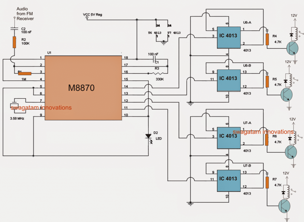
DTMF Receiver Stage
Since the above explained DTMF transmitter circuit uses an FM topology, the receiver must be an FM based too, for capturing and processing the transmitted data.
An ordinary FM radio or a receiving card is all what is needed for collecting the transmitted info from the transmitter unit.
The received DTMF audio by the receiver is next forwarded to a standard M8870 DTMF decoder circuit stage which effectively detects and processes the DTMF data received by the FM radio.
As per the specifications of the IC, its outputs correspondingly switch ON and OFF in accordance with the DTMF tones generated and transmitted by the transmitter stage.
The above switching of the outputs of M8870 IC is integrated to 4 discretely configured IC 4013 based flip flop stages which respond by toggling the attached relay driver stages.
The relays can be wired to the relevant loads for achieving the intended switching via the DTMF transmitter handset.
Receiver Circuit DTMF


Questions & Answers
Hi Swagatam,
I don’t want the relay to toggle, but only be active only as long as there is a signal. Can I avoid the IC 4013 and connect the M8870 output directly to the transistor base (through the 4.7k resistor) ?
Thank you!
Hi Yosua, you can do that. Connect the relay driver transistor bases directly to the IC outputs via 4k7 resistors.
Good Day Swagatam
I am interested in DTM receiver side only if it can be activated by HAM handheld radio which includes DTMF board?! Actually I need simpler one with only two outputs as I need it for different project. Are you also manufacturing these PCB’s and if you do what is the price
Hi Neno, sorry presently we don’t manufacture PCBs.
Plz swag i have problem with gsm phone remote plz my circuit work but the only problem is that when i use my hand to tourch the jack the led grow and the relay activate also when i use normal wire to tourch the jack it still led and relay still grow instead of rington what is wrong plz
Hi Mark, which circuit are you referring to?? please post this question under the same article, I’ll check it….
Hi Swagatam,
Thanks a lot for helping out… 🙂
God Bless 🙂
you are welcome mistral.