This is a simple rain sensor circuit which can be built by a school grade student very easily and can be used for displaying its relatively useful feature, probably among his friends or in a science fair exhibition.
Using IC 555 as the Comparator
The circuit is basically rigged using IC 555 as a comparator and is typically configured to sense the low resistance through water across its relevant inputs.
Let’s try to understand how to build a simple rain sensor circuit using the IC 555:
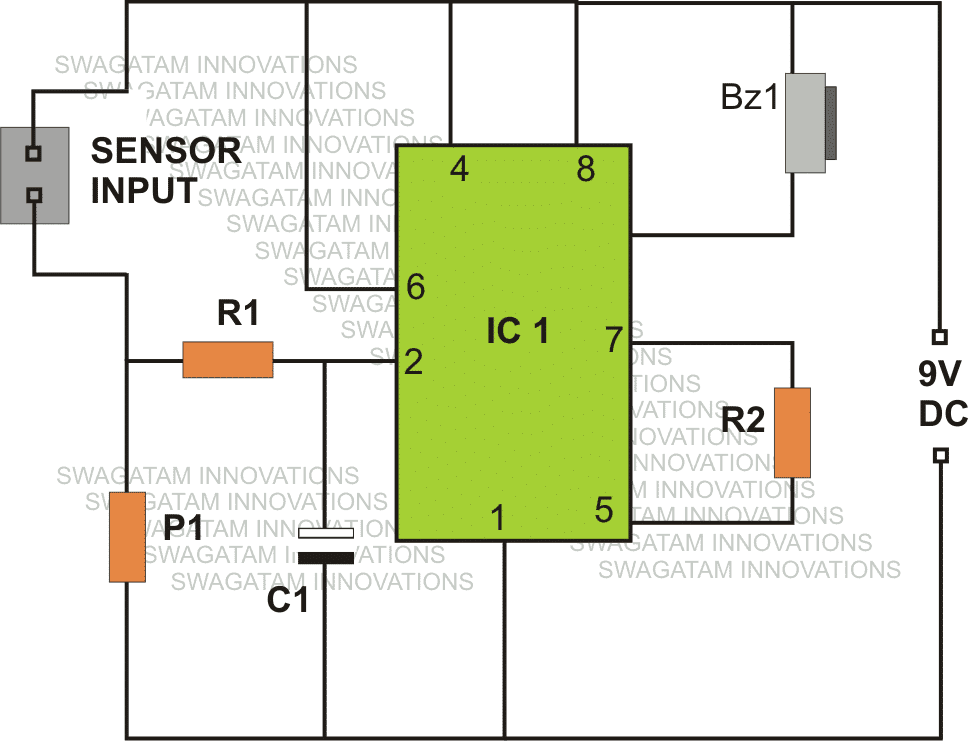
Referring the figure, we see a rather simple design made around a single active component which is the IC 555.
Other than the IC, the circuit just includes a few cheap passive components like resistors and capacitors.
We are familiar the two important modes of operation of the IC 555, which are the astable and the monostable multivibrator mode, however the IC is laid down in a rather unusual fashion, quite like a comparator.
How it Works
As shown in the figure, sensing terminals are received across the positive and pin #2 of the IC via R1.
When water (due to rain fall) comes across the above inputs, a low resistance is developed here. The preset P1 is suitably adjusted such that any type of water across the sensing inputs triggers the IC appropriately.
The sudden low resistance at pin #2 of the IC acts like a pulse which exceeds the potential at pin #2 more than 1/3 of the supply voltage.
This activation instantly makes the output of the IC go low, ringing the connected buzzer. The buzzer circuit is comprehensively explained here, if you wanted to build one.
As long as the sensing input stays immersed under water, the output continues with the above situation.
However the moment, water is removed from the specified input terminals, the potential at pin #2 reverts to less than 1/3 of the supply voltage, making the output go high, back to its original position, switching off the buzzer.
The above operation effectively indicates the commencement of a rain fall when the sensor is appropriately placed for the detection.
The charge inside the capacitor C1 keeps the buzzer ringing for some period of time even after the water from the sensing inputs is completely removed.
Therefore the value of C1 must be appropriately chosen, or may be completely eliminated if the feature is not required.
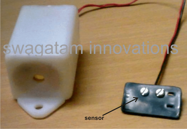
Making the Sensor Unit.
The explained rain sensor circuit obviously needs to be placed indoors, therefore only the sensor terminals are required to be positioned outdoors through long connecting flexible wires.
The figure shows a simple way of making the sensor unit.
A small plastic of around 2 by 2 inches is used and a couple metal screws are fixed over the plate. The distance between the screw should be such that no residual water is able to stick or clog between them and water formation across it is detected only as long as the rain fall persists.
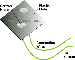
The wires from the screws should be carefully terminated to the relevant points on the circuit. The circuit must be hosed inside a suitable plastic enclosure along with the buzzer and the battery.
Parts List
R1 = 1M, R2 = 100K,
P1 = 1M preset, can be replaced with a 1M fixed resistor
IC = 555, C1 = 10uF/25V,
Simple Rain Sensor Circuit using a Single Transistor
If you think the above circuit a bit over complex, then perhaps you could implement the design using a single transistor and a resistor, as shown in the following image:
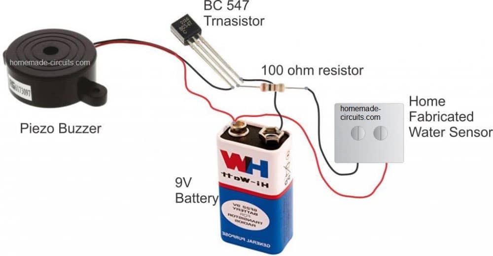
The working of the above circuit is rather simple. When water droplets or rain droplets fall on the sensor device, made using screw heads, the water bridges across the screw heads allowing small electrical current to pass across the metal, triggering the base of the transistor. As soon as this happens, the transistor begins conducting and amplifies the conduction across its collector/emitter terminals.
This results in the switching ON of the connected buzzer which now begins buzzing or beeping indicating the commencement of rain outside, and warning the user regarding the same.
Rain Sensor Oscillator
The above circuit requires a ready made buzzer, because it does not have its own oscillator circuit. The following two transistor version employs its own oscillator and therefore a ready made buzzer is not required. Instead a small 8 ohms speaker will suffice and can be used for generating a sharp tone whenever a rain fall is detected.
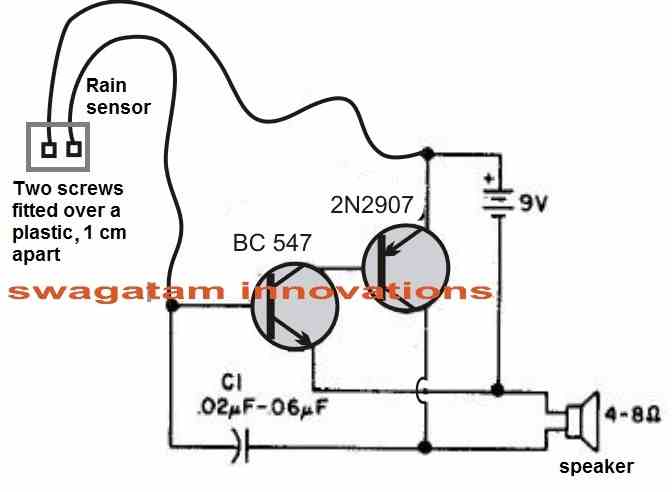
The sensor unit is again built using two metal screws fitted over a plastic base, around one cm apart.
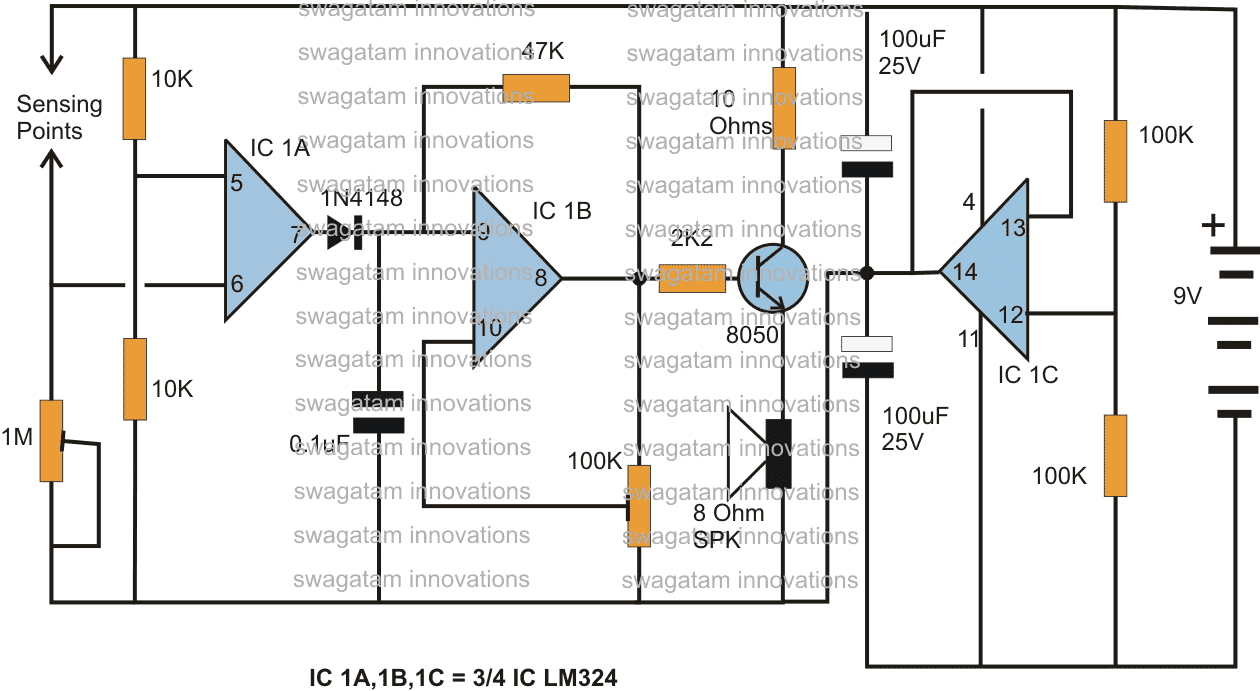
Alternate Rain Sensor/Alarm Circuit Using the IC LM324
An alternative version of a rain alarm circuit can be seen below using a single IC LM324

Comments
Can design the rain sensor myself
yes you can design it
Hello,
Nice circuit post. I would like to know the expected difference in performance between the 555 and transistor designs. I need to sense rain water using two stainless steel screwhead probes with about 3/8″ (9mm) spacing between them.
Thank you,
Chris
Hi, thanks for liking the post! The 555 will produce sharper conductivity as soon as water is detected between the probes, regardless of the distance between the sensing probes, whereas the response of the transistor will not be as sharp, and its conductivity will depend on the load current and the distance between the sensing probes. As the probe distance increases the transistor conduction decreases and vice versa.
I need more simple circuit designs.
Respected sir,
I did the following circuits for my own use
https://www.homemade-circuits.com/wp-content/uploads/2019/10/IC-555-water-supply-alarm-circuit.jpg
i did as per the circuits diagram . when i switch on the circuit a permanent humming sound is coming from the speaker . hence i have changed speaker . i used 9 v battery. kindly help me to solve the problem
Thank you
yours faithfully
good morning sir
i will try and tell you later.
thanks for your immediate help
You are welcome!!
sir ,
tested as per your guidelines, no response from that , replaced new NE555 . it is working well.
you are master
thanks sir
r.bala
Glad it worked bala, please keep up the good work!
yes sir
thank you
Bala, connect a 100K resistor between pin7 and pin6/2, if you get an alarm sound then your circuit is working OK. After this you can remove the 100K and bring water between the 56K resistor and pin6/2 to verify the same results. If you are nor getting any sound output then your IC may be faulty or there could be some other connection error.
Thanks Sir. Circuit works well on the breadboard.
you are welcome Rooh, glad it worked for you!!
Can I use this with 12V power circuit to ride in a vehicle, to drive the windshield wiper
yes that's possible, just replace the buzzer with a relay and use the relay contacts with your wiper motor switch
Yes same circuit and it worked flawlessly…
Hey do you apply the exact circuit???
Hi, thanks for your interest….. however all connections in the above design are correct, pin3 is connected with the buzzer. The design has been tested number of times with perfect results.
Good day,
You can try measuring the resistance of snow one inch apart, if it's around 300k then this circuit would do the job for snow too.
Please explain me the whole design requirement, I'll try to hep.
All the components are extremely low cost.