This circuit will allow you to control any electrical gadget from any part of the world through your cellphone remotely, that too without spending a penny for the individual commands.
Circuit Concept
Whether it’s you vehicle, your basement door, your mansion gate or simply the air conditioner of your house, everything can now be switched by just a flick of your cell phone button.
And yes, it’s completely fool proof, meaning no false triggering is possible through any other cell phone signals, it works only through the owners cell phone commands.
The explained circuit must be employed strictly for operating only the following specified equipment:
All domestic electrical appliances like, lights, fans, motors, TV sets, refrigerators, Air conditioners, washing machine, porch lights, garage door, house gate, basement gate or entrance, car ignition, car doors, water heater etc.
The concept has been already discussed in one of my previous articles – How to make a GSM car security system, and the going about is unbelievably simple.
However, the above article deals with a system that involves DC control features and therefore is not suited for controlling AC appliances.
The unit discussed here is a universal device and can be used for operating all types of electrical gadgets from any part of the globe, just by making a single blank call to the systems number.
The system will faithfully respond to every call made from your cell phone and will alternately switch the connected load ON and OFF as per your instructions.
The concept is impeccable, as it has been tested by me thoroughly since last three years with flying results.
Basically the unit employs a very fundamental principle of converting the ringtone of a cell phone into a command output for operating a relay.
This cell phone acts as a modem and is permanently attached with the internal control circuit of the unit. The modem cell phone is initially made ready by putting a SIM card inside it and by configuring the essential assigned numbers into its phone directory.
These assigned numbers are the only numbers to which this modem responds. Therefore you would want to assign only those numbers through which you may like to make a call to the “system”.
For safety reasons more than one number is assigned to the modem so that in case one of your cell phones is out of order or has low battery, you always have the option of using the other cell phone for triggering the system.
The biggest advantage of the GSM cellphone remote control circuit is that, any cheap NOKIA cell phone can be used here as the modem and therefore there’s no fear of the modem becoming obsolete.A simple yet effective cell phone remote control switch details has been discussed here with complete schematics and step by step tutorial.
UPDATE:
Looking for an advanced solution? Read more below:
Advanced Microprocessor Based GSM Remote Controller
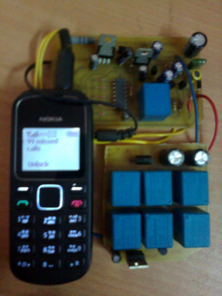
If you have sufficient prior knowledge of electronics, you should be making this complete unit within a days time. Let's begin the discussion. Basic Concept The idea here is to use an ordinary NOKIA 1280 cell phone as the modem attached permanently with a switching circuit. This entire unit now becomes the receiver unit.
The modem cell phone NOKIA1280 is assigned with desired numbers, for example the owners cell number and a few other numbers of the owners family members.
When the modem cell phone is called through these assigned numbers, the modem ring tone becomes active and this ring tone is applied to the control circuit and is processed for operating a relay and the connected load.
Since the modem cell phone needs to be attached permanently inside the switching unit, it needs to be charged at regular intervals so that it remains functional all the time.
For this, a separate cell phone charger module has also been incorporated along with the main circuit which keeps the modem cell phone battery always up to date and fully charged.
It is quite obvious that the attached cell phone modem will need a SIM card, which will need to be maintained as we do for normals cell phone operations.
I have explained the building process. You will have first get or procure the following materials or parts for making this unit. I would suggest not to make the Printed board initially, it would better to first test the working over a general board and if thing goes then you would want to transfer it over a well designed P-C-B.
Bill of Materials
All resistors are 1/4w 5% CFR unless otherwise stated.
- R1 = 22k
- R2 = 220 OHMS
- R3,R11,R12 = 100K R13 = 100 Ohms
- R4,R6,R7,R9 = 4.7K
- R5 = 1K,
- R8, R10 = 2.2M
- C1,C4,C5 = 0.22uF DISC TYPE
- C2,C3 = 100uF/25V
- T1,T2,T4,T5 = BC 547B
- T3 = BC557 B
- ALL DIODES = 1N4148 IC1 = 4093
- RL1, RL2 = RELAY 12V/300 OHMS SPDT
- JACK = 3.5mm AUDIO JACK
- CELL PHONE MODEM = NOKIA 1280
Circuit Diagram
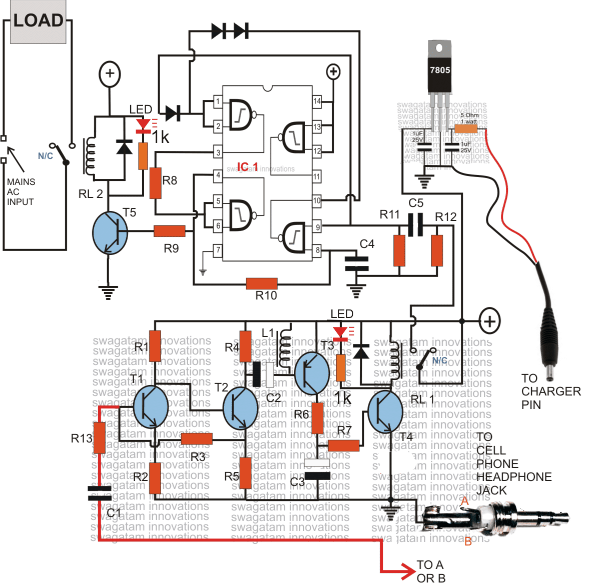
Understanding the Schematic Diagram
The above schematic of the proposed cellphone controlled remote circuit is rather very easy to understand. It may be divided into two main stages, the lower stage consisting of the transistors is a simple audio amplifier, the upper stage consisting of IC is the flip flop triggering stage.
When a signal is present at the 3.5mm jack, which might be the input ring-tone from the cell phone modem., T1, T2 amplifier to some greater level, which is further amplifier by T3, T4 to a level is becomes sufficient for triggering the relay RL1. RL1 instantly connects the supply to the input of the flip flop at C5, via its N/O contacts.
Note that RL1 will remain switched ON as long as the ring tone is present and will switch OFF the moment the ring tone or the signal over the 3.5mm jack is canceled. C3 makes sure that the relay does not get rattled by any insignificant signals or RFs.
L1 has been installed also for the same reason, that is for eliminating unwanted signals and making sure that T3, T4responds only to valid ring-tones.
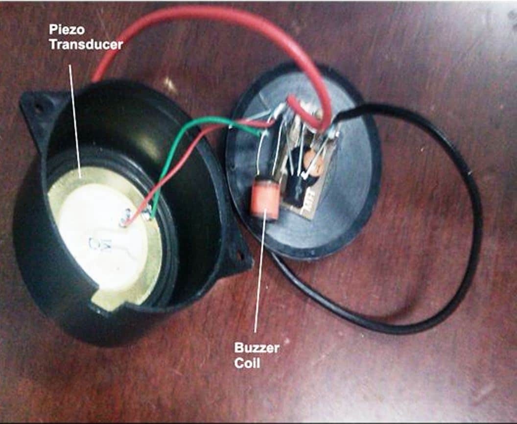
L1 is a buzzer coil, as used in piezo electric buzzers, or may be hand made by winding 1000 turns of 36SWG super enameled wire over a small ferrite core, size and shape does not matter. Image of L1, inside a buzzer
The period for which RL1 remains switched ON will have no consequence on the flip flop operation, the flip flop will switch ON and OFF in response to every subsequent missed call made from the owners cell phone.
The section comprising the IC 7805 is battery charger section, which needs to be connected to the battery charger input of the cell phone.
The charger will keep the cell phone battery always charged so that it remains functional all the time. The above circuit has been thoroughly tested and confirmed by me, so if you make everything as shown in the above diagram, it should start working immediately.
How to Assign Numbers Inside the MODEM CELL PHONE It's very easy. Just follow the following steps. Save the names and the numbers which are important and through which you want the above unit to be operated.
Next select a particular name-->--press scroll right-->--"contact details" will be displayed-->-- press options-->--scroll down-->-- select "assign tone"-->--select a ring tone which has a sustained, non-breaking tune-->-- do OK. Repeat this for all the desired numbers. Now go to settings, go to tone settings and select "empty", press OK.
That means now you have switched OFF the default ringtone and no ringtone will be audible for any numbers other than the above assigned ones.
So you can be rest assured that the system will not respond to wrong numbers or any unknown numbers. It will respond to only the calls made from the assigned numbers.
How to Power the Unit
The circuit needs to be powered through a DC12V/500mA or 1 Amp SMPS adapter.
The load may be any electrical appliance like lights, fans, AC, fridge or anything that you may like to switch using this system.
Video Clip showing the circuit functioning of the prototype
WARNING AND DISCLAIMER – THE PROPOSED DEVICE MUST BE USED FOR OPERATING ONLY THE COMMON HOUSEHOLD ELECTRICAL SYSTEMS AND PARAMETERS. THE PROPOSED CELL PHONE OPERATED SWITCH MUST NEVER BE USED FOR ANY OTHER INTENTIONS OR PURPOSE WHATSOEVER, AND THE AUTHOR TAKES NO RESPONSIBILITY FOR ANY LOSSES THAT MIGHT OCCUR IN CASE THE UNIT IS USED FOR OPERATING ANYTHING ELSE OTHER THAN WHAT'S BEEN SPECIFIED IN THE ABOVE ARTICLE.
https://www.homemade-circuits.com/wp-content/uploads/2011/12/4093-flip-flop-circuit.pn hello ji 1. Sir, the small ring of the cell phone turns on the relay due to which the load starts when the 4093 receives the trigger. I want the load on the long ring to be on, 2. Cellphones audio stage. If there is a lone time power cut, when the light comes on, the relay remains on for about 8-10 seconds until the capacitor gets discharged, if there is any solution, please suggest. thank you sir
Hello Mukesh,
The 4093 relay will be triggered ON, if the audio stage relay turns ON, so we have to stop the audio stage relay RL1.
I think you are using the following circuit:
" rel="ugc">
Your first problem can be solved by adding a delay timer at the input.
For the second problem, please check whether the relay remains ON for 8 seconds when the mobile is connected with the audio stage or also when it is removed from the audio stage.
Please check this by first keeping the mobile phone connected, and then check again by keeping the mobile phone disconnected.
" rel="ugc">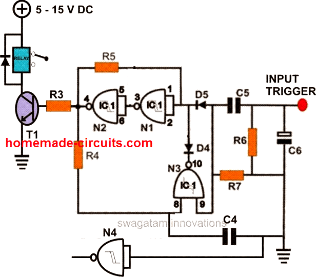
Sir, in this circuit 4093 is working fine and the circuit is also working but the voltage spike is not being controlled.
Secondly, I have made a cell phone based circuit 5 years ago and it was working well. Now due to a problem, I have to make another one. So there is no flaw in your circuit. Now I am facing problem in making the circuit. So I am expecting your help if you want. Thanks.
Mukesh, I completely understand your problem, and I will try my best to help you out.
However, protecting a CMOS based flip-flop circuit can be very difficult especially if the spikes are generated by a high power AC motor.
I am sure the spikes are being generated by your pump motor.
You can do one thing, please replace the R5 resistor with 100k and replace C6 with 470uF capacitor, and make sure you have a 1000uF/25V connected right across the supply terminals of the IC 4093, along with 0.1uF and 1N4148 diode.
Please check and let me know.
Sir in gsm cellphone circuit when trigger is given on C5 the relay turns on once and turns off immediately. I have made 5 boards, all have same problem, boards are separate, fixed 12v input supply, all components are new, IC is ok because it is working properly in your other circuit, I have installed 100uf/25v on pin 7 and 14, and C 0.1, 4148 perllel, still the relay does not stop on triggering, it turns off immediately. Please tell me a solution. Thank you
Hello Mukesh,
I have checked this circuit thoroughly in jeweler shop, motorcycle and car, for me it worked perfectly in all the occasions.
You said it is working OK in other circuit, which other circuit are you referring to?
" rel="ugc">
Sir this circuit is working very well but when the light is switched on sometimes the relay gets on automatically and sometimes not, it is a separate circuit and a push switch has been installed, along with that 100uf or 0.1 have been added from the trigger point as in the circuit, input 12v/ 1amp. Full bridge rectifier plus filter 1000uf/25v, and supply has been given from IC7812.
Thank you Mukesh, for updating the results.
Actually, any circuit with CMOS ICs can be vulnerable to atmospheric noise interference (RF). IC 4093 is also a CMOS IC and therefore can be prone to RF disturbances.
Please try this: Supply the output from the 7812 to the 4093 through a 100 ohm resistor.
Also, Connect a 1N4148 diode in parallel with your 100uF or 0.1uF diode. Let’s see whether this helps to suppress the RF noise or not.
Make sure all the wire connections between the parts are as small as possible.
I hope you are not making it on a breadboard, because breadboard uses long wires, which can easily catch RF noises.
…please note, 100uf or 0.1 must be connected across the supply terminals pin14 and pin7 of the IC…also add a 1N4148 across the supply line. Cathode to pin#14 and anode to pin#7.
Sir, the 4093 board is made separately. I am touching the positive with a wire. The relay turns on once and turns off immediately. It does not stop. If a capacitor is connected between pin 1 and 4, then the relay works properly. Without connecting it, the relay does not stop. But on doing this, sometimes the relay turns on automatically when the light is switched on. This is a serious problem. The transistor and IC are OK. The board is also separate.
If the 4093 is getting activated by touching the positive line, that means something is wrong with your circuit or your power supply.
A capacitor between pin1 and pin4 is not required. Please try adding a 100uF capacitor directly across the +/- supply pins of the IC 4093 and also connect a 0.1uF directly across the supply pins of the IC.
Please refer to the following diagram and make sure all the components are connected correctly:
" rel="ugc">
Let me know how it goes…..
Dear Sir, pls help.
Sir I made this circuit about 5 years ago which was working properly but a month ago I am facing a strange problem in which the relay led remains on permanently. Even after trying everything and reading all your comments the problem still persists. Then I made a new pcb in which on touching +ve with the wire the relay turns on once and turns off immediately. This had happened 5 years ago also for which I connected a c 224 or c 100uf 25v in parallel between pin number 1 and 4 of cd 4093 so that on coming of light the relay would turn on once and turn off immediately but the relay would not turn on unless it was rung. I have made a new board also same to same and it is working properly but the biggest problem I am facing is that when there is fluctuation in light the relay turns on automatically and the farm motor turns on and will not turn off unless it is turned off. Sorry sir I think there is a problem of ic 4093 in the circuit. Some part is missing between pin 1 or 4 because unless we add C 224 between pin 1 or 4 the relay will not turn on under any condition. Please the relay should not turn on automatically when there is light fluctuation and the relay should turn on when we turn it on without C 0.22 between pin 1 or 4 of CD4093.
Thanks
Hello Mukesh,
Thank you for your feedback and for testing this circuit.
If the input trigger relay is always ON, that means the transistor driver circuit has some problems, the 4093 is absolutely fine. The 4093 circuit cannot be faulty, you can check it separately using a push-button. Here’s the schematic of the 4093 circuit which has been verified by me thoroughly:
" rel="ugc">
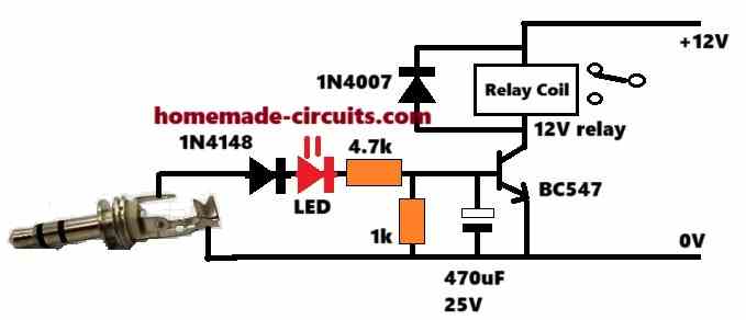
For the transistor relay driver circuit, please try the following circuit and let me know how it works. We can improve it until it works perfectly. Please first try and confirm this relay driver circuit separately, without connecting it with the 4093 circuit:
" rel="ugc">
Please update me with your findings.
Hi, Mr Swagatam I have CD4027 IC with me how can i connect it to REPLACE CD4093 so to archieve this? Please help me!
Hi Bobtone, those two ICs cannot be replaced with each other.
I have several King Pigeon GSM relay boxes that I use to reboot devices when there is no Internet available. They have worked great until recently because of the move to 5G. They use GSM technology and are supposed to work with 4G but not in this country. Does your device/system work with the newer cell service?
The circuit explained in the above article uses the ringtone from a mobile phone for the required triggering. The mobile phone can use any SIM 4G or 5G that won’t matter as long as it is providing the ringtone to the detector circuit.
Do you sell a completed unit? Don dniebrugge
Sorry we don’t sell readymade kits
Please Sir, what modifications do you make to control more loads say about 5loads with 5 relays for home appliances.
You can connect more relays in parallel that will allow more loads to be connected in parallel
Interesting circuit! Do you have a value for L1? Looking to purchase a choke, rather than scavenging an innocent buzzer!
Glad you found it interesting. My inductance meter shows 48 mH for this coil, so anything between 40 and 100 mH would work nicely.
Hallo. I assembled all the parts as per the schematic. The lower part(amplifying circuit) works very well. The problem is with the flipflop circuit. When a call is made, both circuits goes on but the moment the call ends, both circuits goes off. Please assist as soon as possible.
Hello, you can isolate the flip flop section and check it separately to locate the fault. Please refer to the second design shown in the following article:
https://www.homemade-circuits.com/build-these-simple-flip-flop-circuits/
It is the same which is used in the cellphone design. Please ensure everything is connected as per this design, you can manually check the flip flop action by touching the input trigger point with the positive supply line, each alternate touching should make and break the relay operation. Once confirmed you may connect the input trigger with the RL1 contacts of the cellphone circuit for the final testing.
Thanks for the feedback. I connected the same but the only difference is that I never found a disc type capacitor of 0.22uf and instead I combined three 0.1uf ceramic capacitors in parallel. I also used a power supply adapter of 12v 3A. Can that be the problem?
I would also like to know which components are responsible for holding the two states.
That will also work, using 3nos 0.1uF instead of 0.22uF is fine. In the link which I referred previously you will be able to find the full explanation regarding the working of 4093 flip flop, it is a tested design. Actually it is C4 that is responsible for holding the two states, along with the gates N1/N2.
12V/3A is perfectly OK, in fact any voltage below 15V is fine, current is not relevant, it can be any value higher than 500mA. Make sure the relay coil resistance is not less than 200 ohms if the transistor is BC547
Please what IC did u use in the circuit and the voltage of the relay
IC is 4093, relay coil voltage will be as per the supply voltage, preferably 12V
Please Sir, could it be possible to control individual house hold appliances using this device?
And if possible, what are the possible modifications to be made?
No, you can control one device or many devices simultaneously but not individually…
Sir
The nokia phone with me is Model no. 101 Type RM769.
Is it suitable ?
Is it possible to on off more than one relay?
Mathew, I think it should work, however only a practical test can confirm this, yes you can apply more relays in parallel by appropriately upgrading the driver transistor
Please Sir, what to do incase you want control each appliance separately?
So that you could select those you want them to stay on, and off those you would not need at a particular time.
Hi Lawal, it is not possible with this design, you may have to search for an Arduino based design
Sir,
I want to control 5-6 different LEDs and motors via phone.
I mean one phone should e connected to the motors or LEDs and via other phone with help of any app I can switch to those LEDs. with any limit.
please heelp me sir..
Hi ankitesh,
you can try the following concept
https://www.homemade-circuits.com/dtmf-based-fm-remote-control-circuit/
in the first circuit remove the 5089 and the key pads instead feed the transmitter from your mobile earphone jack, and with DTMF app activated
Sir i have achieved the task but RL2 is making continue unwanted noice. What should i do ?
Isolate the upper 4093 circuit stage entirely by disconnecting it from RL1, and check it separately by manually by touching R12/C5 to the positive line, this should alternately switch RL2 ON/OFf, first check and confirm this.
Sir I tested 12 volt at C5 from N/O contact of RL1 but my LED across RL2 is continue glowing with vibration & sound in RL2.
That means you have done some mistake in the flip flop circuit.
you can refer to the following articles and do the required corrections or make a different flip flop design using IC 4013
https://www.homemade-circuits.com/2011/12/build-these-simple-flip-flop-circuits.html
https://www.homemade-circuits.com/2012/05/make-this-easiest-flip-flop-circuit.html
Dear Sir,
Thanks a lot for immediate response. Sorry for frequent queries but I need your guide.
My part 2 sometime works. But the LED glows when I touch my body part like finger or thumb to rest part of PCB. I think it requires PCB to be grounded. But I made all connections as per above circuit. I have two seperate PCBs with IC CD4093 for same connection but same problem persists for both. I think there is continue supply on Pin 4 then LED continue glows by making finger connection to PCB.
There is a problem to use IC CD4013 because I lives in remote rural area so its not available easily. If I order this online then it will take more than a week to deliver so i can’t wait.
I hope to immediate response.
Pushpendra, if you compare the 4093 circuit from the other link I provided and the above 4093, you will find that a capacitor from the input trigger to ground is absent in the above design which might be causing instability, so you can add this capacitor and see the results.
see how C6 is added for stability in the 4093 design under this article:
https://www.homemade-circuits.com/2011/12/build-these-simple-flip-flop-circuits.html
Dear Sir,
Now i completed almost 90% task. The only problem is that relay RL2 activates with single time trigger pulse but deactivates with multiple time pulse. I think there is some residual current at output. What should I do ? Please help me sir.
Pushpendra, did you connect “C6” as advised by me earlier? If yes then now try connecting a resistor parallel to this capacitor..the value can be anywhere between 10K and 100K
Sir i have made the circuit but i didn’t get result. would you like to help me on +919887095742. I Need urgent help.
Pushpendra, sorry a telephonic conservation won’t be possible, the above design is thoroughly tested by me but please note that it will require an experts knowledge to complete this project and is not recommended for newcomers, so please move ahead with caution,
The first relay goes on clicking and the secomd relay works only when the audio.jack is touched. And does this circuit only works with nokia phones. Please explain
Helo SwAGATAM the circuit works great with battery powered but when i use smps adapter 12v 1A it behave crazy and relay 2 switches on the connected load have failed to triubleshoot this i tried puting resistor on + of smps but failed please help me because i want to use that adapter than battery
Thanks Davis, if your relay is making noise, you can add a capacitor parallel with the relay coil
you can add more relays in parallel, but make sure the transistor is upgraded appropriately to handle the relay coil current
Helo SWAGATAM thanks for that great circuit. I made it and works fine using battery but when i change and power it with 1A 12V smps adapter Relay2 activated and switch on load and makes even sound. Help me coz i want to use smps adapter rather than battery. Also help me how to connect other relay to connect multiple appliances. Thanks u great
Thanks Davis, if your relay is making noise, you can add a capacitor parallel with the relay coil
you can add more relays in parallel, but make sure the transistor is upgraded appropriately to handle the relay coil current
Hello Sir,
This is a great Circuit, I want only connection during phone ring, every time. Pls help, i am very exited,
Thanking you In advance !!
Hello Sir,
can you advise me whether i can use SFM-27D electronics buzzer coil as L1?
Hello Saji, if it is same in appearance to the one shown in the image then it would work
sir can u plz give me a simple ckt diagram bcoz i am beginer and also i want one pick of ur project that will help to buy component sir i hope u will help me
swapnil, you can try the following circuit
https://www.homemade-circuits.com/2012/01/how-to-make-simple-timer-circuit-using.html
Sir i want to use such a circuit for 3 phase 5HP motor. Can i get circuit diagram and details video please..!
use 3 parallel relays for REL2 and connect the motor across the 3 contacts of these relays,
how did rl1 get on its one pole is connected to vcc and other to t4
Hello sir,
I have build the bottom part of the circuit.
When I touch C2, the relay and LED turns on. So, as your suggestion in other comment I connected 0.1uF capacitor in parallel with L1. Now there is no more problems in that.
But in either case, if I have 0.1uF capacitor in parallel to L1 or not, I never get my relay or LED turn on when phone rings. What should I check?
I have used 390uH coil in place of L1.
Hello Vishal, though very strange, it seems the audio signal is not powerful enough to drive the relay….you can connect an LED parallel with the relay coil with a series resistor and check if this LED lights up or not…this will prove whether the signal is weak or the relay is incompatible.
If possible I'll try to update another easier and a foolproof design soon.
Thank you for reply sir,
As shown in the above circuit, I connected the LED. But the above LED is not lighting up.
When calling If I check voltage on Audio Pin, I get 0 Volts.
Vishal, keep your meter in the 200mV or 400mV range whatever may be the range available in your meter but make sure your meter is in the AC range….and now measure the voltage of the ringtone without connecting it with the circuit….
the above design is just a basic concept for understanding which can be enhanced in many different ways:
electricity failure problem can be easily tackled by adding a small battery back up for the circuit, so that the missed call operations from the user works perfectly regardless of the mains availability.
the call-back alert feature has been already elaborately discussed in one of the similar application concepts as given below:
https://www.homemade-circuits.com/2011/12/build-homemade-gsm-car-security-system.html
the feature is also separately discussed below which could be easily included in the above design
https://www.homemade-circuits.com/2012/04/make-this-cell-phone-call-alert.html
Have you done any modifications?
I have another idea over missed calls.
Generally in farms there is problem of electricity.
In this case, please note:
1. If farmer gives a missed call to gsm module, the motor starts.
2. When electricity is cut by government, motor stops.
3. Electricity comes back but motor stays off.
4. Farmer is not aware of steps 2 and 3.
5. Farmer gives a missed call to gsm module to stop the motor, but actually he gets his motor started. And here our system laks intellegence.
So, a possible solution would be:
When farmer gives a missed call, then motor should start. When farmer gives a missed call again, the motor should stop. But this time he should get a missed call back from gsm Module to the mobile he called. Also when electricity fails there should be a battery. At the time of electricity cut, the farmer should get aware by giving him a missed call. Can you implement such a logic in your newer version?
Also the motors used by farmers are 3 phase. So, there should be some thing that a farmer should know if he has electricity available in all the three phases or only single phase.
hi. I have build circuit. but when iam testing lower amplifier circuit the RL1 sometimes responds correctly to calls. sometimes RL1 switches on when dc power is switched on. what is the problem?
if RL1 switches ON momentarily during power switch ON then that's not a problem, it could be a sudden transient, you can try adding a 0.22uF capacitor parallel with L1 to rectify this…
but RL1 must respond always to each and every call…
hi. I made my lower circuit to work. but I want to know the exact operation of lower circuit. and also how can I test upper circuit before connecting it to lower circuit.Thanks in advance.
the upper circuit details are given in the following article, read the 4093 explanation, you can check it as explained
https://www.homemade-circuits.com/2011/12/build-these-simple-flip-flop-circuits.html
the lower circuit is just a simple transistor amplifier…with each transistor amplifying the previous transistor signal to a greater level
When i give call to phone, relay ticks and led glows both relay and led is on until i dont disconnect the call. Is that ok? Or correct operation? But if i see your video in that the green led is on for little time but in my case led remain on till call is connected.
It is correct, in my video I might have cancelled the call or I might have used a "one beep" ringtone in the modem, it was created a long time ago I don't remember now..
Sir is ground mence -ve
How I can get total circuit except mobile
Hi…. can i use 220nf instead of 0.22uf and diodes like 1n4007 ????
0.22uF and 220nF are one and the same…so it's fine. 1N4007 will also work
0.22uf cant find… may use 220nf ???
Hello sir, I am working on this project of yours and i need some help. Is it necessary to use nokia 1280 or any other set can do ??? please help …regards Mohit
Hello Mohit, any phone which has an "assign tone" feature will work for this project.
Dear Swagatam, As I could not debug the problem in the the vibration detection based circuit I decided to go for this one. I assembled the circuit(the lower part or the amplifier only) on bread board. When powering on the the RL1 and the associated LED is getting activated by default(which should not happen if the circuit works properly). Well then I went through the comments section and found once you said to put a .1 mfd cap. across the buzzer coil legs. I did that. Now the RL1 and associated LED is not turning on by default but it is not responding to ringtones neither. Surprisingly the if the A or B and the ground connection of the earphone shorted the led and the RL1 turns on and remains turned on as long as the two points of the earphone remains shorted. I know from this behavior you will be able to suggest proper correction to be made to the circuitto get it worked. Please help. Wish you happy and prosperous 2016 ahead.
Dear Sanjoy,
I am sorry this problem is not familiar to me, because I never encountered such an issue while making the design, I have already made hundreds of these circuits and none gave me the mentioned issue, so I am clueless about it.
first of all the coil L1 and the associated capacitor have no direct relation with the circuit triggering, the circuit should work even without thees components, these were introduced to prevent accidental and false triggering each time the charging was imitated internally which strangely created unwanted RFs and triggered the relay spuriously, so by introducing L1 and the parallel capacitor completely eliminated this problem, so this cannot be relevant in your case.
The problem could be somewhere else in your connections, or may be the cell phone is not generating sufficient input voltage, make sure it's minimum 100mV from the cellphone headphone, otherwise the circuit might not respond.
Wish you too a very Happy and a prosporous 2016 🙂
Sir,
I have a weird problem, the air conditioning unit in the office draws too much current when switched on. The machine can only work for a few minutes before the power feed trips. Can u suggest a circuit that can solve the problem
Setute, the problem could be specific, it won't be possible to judge it without a practical check up…it might need a repair from an expert AC technician..
,
Dear Sir,
I am interested in this circuit.I want to know limit of the motor rating.like 0.5 to 100 hp motor operated with this circuit. total no of mobile no from which this circuit operated.
motor rating will depend on the relay contact rating….both must be rated equivalently.
you can operate it with any number of mobile phones, by assigning the numbers….. as per the given instructions in the article
please could you send me the calculative analysis of the circuit
devashish
ijust want to know how to start 3 phase induction motor using the same assembly
use three relays in place of the RL2 and wire the 3 phases through their contacts with the motor
I am Chandra from Nellore AP Sir first circuit (I mean amplifier circuit) working properly. give misscall glowing LED and RL1 is activate good, but second circuit flip flop is not functioning. it is not work properly give the miscall LED only flash and RL2 is also active and relese automatically within seconds. I also tryed second circuit of flip flop but in vain (https://www.homemade-circuits.com/2011/12/build-these-simple-flip-flop-circuits.html). I am living in remote area. so I want to know what is the problem of the circuit (sir I tried above 15 flip flop circuits but no result) please help me sir my mail ID [email protected] please reply me. sir I did ferfectly. but some mistake is the circuit or values of resisters please help me
I have made dozens of the above circuit model, all have worked perfectly
anyway…you can try the IC1 section of the first circuit that's shown in the following link:
https://www.homemade-circuits.com/2011/12/make-simple-electronic-clap-switch.html
include C3, R5 at its pin14 and exclude everything that's associated with T2 and T1 section….
now connect your RL1 output with pin14 of the IC.
Sir I want to extend this concept to operate on 3 phase motor starter (10HP motor)
I am doing farming…due to loadshedding it is very hard to start motor at night time by visiting physically…..
Thanks Ramkesh, I will definitely design it and post it in my website…however it might take a little time to get it posted due to many pending assignments in the line…
Dear Swagatam,
This is with reference to the comment of Mr. Raj Mukherji, January 16, 2013. He explained it very well. In addition, farmer suffered from infrequent power cut (6 hrs ower supply in aprox. 10 irregular blocks) so it is very irritating for a person.
I want to apply this type of circuit for three phase induction motor in my village and it will be make for my village also. I humbly request you to develop the circuit for the walfare of our poor villagers. They are not able to purchase it from market.
I will be greatful to you.
Hi! Thank you very much for your work, greatly appreciated. Could you please give some more information on L1. I'm now using a 1 µH coil. My relais isn't switching though. Could this be the problem? It would be very helpful to have a specified value for this coil, so if you could, please.
Greetings
Hi, the coil must have a value of around 40mH…….1uH is too small, it's like short circuiting the base/positive of the transistor, which will never allow the BC557 to conduct, so it won't work….use a 40mH coil or a buzzer coil as shown in one of the article images.
Hi sir,
Great work done, God bless you.
I am now building the circuit, although I have not finished it yet, I forsee it beneficial.
I have followed carefully all the comments ant replies you and it gives me enlightenment.
Someone asked about the how to receive feed back as to whether the output( pump on farm) is work or not. Is there any additional circuit to that. I really need it.
Secondly, it difficult getting the ic , is there any alternative? I have TDA 16846 will it improvise it?
Thank you.
Thank you Evans,
for getting a feedback response you can try the following concept:
https://www.homemade-circuits.com/2012/04/make-this-cell-phone-call-alert.html
which IC are you referring to? but anyway, only the specified ICs will work for the above explained circuit.
Sir I want to extend this concept to operate on 3 phase motor starter….
I am doing grapes farming…due to loadshedding it is very hard to start motor at night time by visiting physically….. Please help sir….
Sagar, you can use three parallel connected relays for RL2 and integrate the contacts with the three phases of the motor supply
Dear Swagatam, thank u for this innovative circuit. Just completed the circuit on a breadboard and in the first attempt it is working perfectly. I have used stage2 circuit from one of ur previous projects (ir remote switch using ic4017) and lenovo p780 instead of nokia 1280. Your circuits are fullproof!!!!! Thanks again.
That's great Sangit, thanks for updating the results here…appreciate your efforts.
sir how to use this circuit to control 4 wire, 1.3kg torque ,12v stepper motor.?
sorry I do not have any idea about it…
Thank You Sir!!! 🙂 🙂
you are welcome:)
Sir
I have some doubts,which are as follows:
How does L1 eliminate unwanted signals? Is there any tuned ckt. formation? If yes, what frequency is it tuned at?
Is C2 acting as coupling capacitor or is it forming a tuned circuit with L1?
Similarly, how does C3 prevent RF interference? Am I right if I say that C3 offers very low impedance at RF, so voltage across base-emitter junction of T4 is insufficient to drive it?
Why is it required to use PNP transistor for T3 while rest others are NPN?
At what frequency is the whole audio amplifier stage tuned to? What is the frequency of the ringtone?
I would be grateful for a prompt response.
Bhawana, L1 here behaves like a choke, it grounds weak signals and saturates only under strong signals from ringtone. C2 is a blocking coupling capacitor.
C3 is positioned as a filter capacitor, cleans ripple.
PNP in the position of T3 becomes more appropriate for creating a high gain response, similarly the remaining must be NPNs
the circuit is not tuned it'll respond to any audio input above 100mV.
Dear sir
please send me your mobile number [email protected]
Sir there is another question dat is hitting my mind. I would be grateful i u could answer it.
The mobile phones generally have Li-ion battery which are rated at 3.7V . So will it be feasible and correct to charge the battery with 5 V.
Thanks and regards…
Bhawana, all cell phones have their own built-in voltage protection circuitry and will never allow anything undesired to the battery. Moreover the 7805 series resistor makes sure that the current is appropriately reduced for safe charging.
The 3.7 Li-ion cell will require 4.2V to get fully charged.
dear swagatam,
i constructed this circuit on breadboard, i even got the buzzer coil very easily and i assembled this circuit, the last problem was that of powering the circuit, I have neither 12v smps nor any battery. But somehow i managed to get a lead-acid 12v 7ah battery. I powered it using this battery. The relay and the leds were "on" as soon as i powered it. But according to you this should not happen, right?
i could not understand the problem.
later I found that t4 was draining current to emitter and switched relay1 and led without base connection of the transistor.strange? Then i took all the transistor from the circuit and then I tested a basic circuit with each of them (excluding bc557) i.e I connected an led to its collector and then 1 k resistor to the other pin of led and connected the same battery i.e positive to other pin of resistor and negative to transistor's emitter. and without a single connection to the base the transistor, the led was "on", and all the transistors reacted the same. I am not getting the problem, but i those transistor are newly bought and working in other circuit.
please please reply soon,
i am in hurry
thanks,
regards
shadab
Dear Shadab,
It clearly shows that all your transistors are faulty, if they are new it doesn't mean that they cannot be faulty…procure good quality transistors and make it once again, preferably buy original philips make transistors.
Or, if the transistors are OK it means you have not put them correctly, either ways the fault is in your circuit not in the above design.
….you say that the transistors are behaving strangely, conducting even without the base connected, then how can the same transistor work correctly in other circuits????
dear swagatam,
I forgot to tell another thing i observed. The statement i gave " working in other circuit" was true, i.e when i connect the transistor to other circuit of 9 volts and below it works completely ok, but when I power it with 12 volts battery or a 12 volts 1000 ma adapter to any circuit, it starts to behave like that.
thanks,
regards
dear Shadab, BJTs are not supposed to work in that way, so there's something wrong with your components…replace them with new ones, from a different shop.
..
Dear Swagatam,
Suppose if we have fixed this circuit with a normal cfl bulb as load,and we are out somewhere. Then how to verify that the bulb is specifically on or off ?
thanks,
regards
Dear Shadab, this feature is not present in the above design….may be "call back" function will need to be included for getting the required revert message.
Sir, in order to include the message facility can we add another cellphone circuitry so that the on or off state of the load can be determined? Can this be done by a similar methodology or some decoders and dtmf technique need to be used for it?
Bhawana, a text messaging facility may not be possible in this simple design, because sending a text message each time a call is made could be very difficult to implement.
Sending a revert missed call is possible though, but this modification will require the modem cell phone to be opened and two wires joined with its "call button"
Sir i read your projects…and find them really helpful for students like me…
Thanks a lot for finding time to share your knowledge with others.
Could you please explain why the circuit works well only with nokia 1280? why not with others? What actually in the circuit differentiates between nokia 1280 and other cell phones??
Thank you Bhawana!
The NOKIA 1280 has the "assign tone" feature which enables the unit to become foolproof with its operations, with this feature the unit won't respond to wrong numbers…. any cellphone with an "assign tone" facility will work as good.
Thank you sir for the prompt response….
Sir i'll be grateful if u could explain how can this project be further extended in order to make it a big one. Can any more features be added?
You can specify the features, if possible I'll try to include them.
Sir u said that the above circuit is only for dc appliances…but why would it not work with AC appliances? RL2 contacts will still cause making or breaking of the circuit containing the load…so the ckt. should work fine with AC loads too. isn't it?
Hi Bhawana, the DC operation was probably meant for the car GSM security system, the above circuit can be definitely used for controlling any electrical appliance.
Thank u sir 🙂
Dear swagatam
This circuit is very sensitive that drives the relay during mobile charging.
It is also sensitive that drives the relay when you touch the input wire of C1 .
Can you please show me how can I reduce the sensitivity of the circuit to drive the relay during the ring tone only??
Thank you
Dear Sasa,
Did you connect the L1 as indicated in the diagram….also please include a 0.1uF capacitor in parallel to L1…this network will make the circuit stable and unresponsive to spurious signals except the ringtone…
sir i have made this circuit on breadboard but it is not respond correctly…………..RL2 remains on What is the reason sir……….?????????
Shubham., first make sure RL1 responds correctly to the repeated missed calls…initially keep the upper stage disconnected from RL1.
If RL1 works correctly then proceed with the upper RL2 stage.
Sir plz give me the pcb layout of this circuit that is very important for me plz plz sir….nd sorry for my bad english
sorry GS I lost the PCB layout film, so i don't have it now, you can take the schematic to any PCB designer and get the design made from them easily.
When i m connect the supply the relay one is automatically open i cant find problem plz help me
did you call the modem phone….RL1 will stay activated only as long as the call is connected.
tell me which parts are not shown to the diagramme
the circuit is perfect in every way, what is happening with your circuit? is RL1 activating when the modem is called??
i make this circut …but it is not working …..what can i do? plz help me
Thanks for sharing the brilliant idea and circuit,sir.
*Are these 3.5 mm headphone pins available at the stores?
I feel it difficult to peel off the outer sheath of my headphone jack to take the pin out.
*What is the inductance of the buzzer coil used?Could it be replaced by one of the coils of a miniature driver transformer?
*Why T3 is a pnp transistor..?
I'am a beginner..
Regards
-Pranav
Thank you Pranav,
Yes 3.5mm jacks are available as spare with an unscrewable plastic cover.
But this circuit is not for a beginner, you will have to first learn all the basics of electronics, do plenty of practicals with simple circuits and then attempt the the above project.
hello sir .i like your project.. its a wonderfull. i need your big gift.
please send me this project FULL SCHEMATIC
MY G-MAIL–[email protected]
hai sir plz send me this project full schematic
[email protected]
sir, how can i connect relay 1 and relay 2 ….need more
sir you give me the spec of IC4903
Dear Swagatam,
Can You Send this pre packed gadget, i will pay for it
Dear Ajay, presently I am not manufacturing this unit so I am sorry I wouldn't be able to send it to you.
Sir
Can we use a camera mobile phone with 3g support to receive a video call from the user after a alert call been made ?
I don't think it would be possible using a simple technology as above.
The same problem is faced by me… Only for lower circuit it can not enrgies the relay…
Sir my circuit is not working….i have made ur previous project in which the circuit is on for only a short period till the phone rings i.e half part of dis circuit…. Without relay it is working properly bt when i connect relay it can not switch the relay….
I cant understand y it is happening so….
Plz help me…
My email id is [email protected]
Deepak, you should make and test the upper flip flop circuit separately for confirming its operations. Once it's confirmed you may proceed to integrate it with the lower section. You may refer the second circuit from the following link for a detailed info regarding the flip flop circuit design:
https://www.homemade-circuits.com/2011/12/build-these-simple-flip-flop-circuits.html
you mean that there are 3 dc adapters or 1 only gives the 3 rails
all (+) to be made common and joined with the (+) of the power supply, same for the "earth" rails.
how the +ve sign is a dc supply connected from only one side
how the +ve sign is a dc supply connected from only one side
I did not understand your question…
I mean why the dc supply has only one branch ( +ve only )
and not 2 branches +ve and -ve )
The lines with the earth symbols must be all connected with the negative of the power supply.
another question mr Swagatam did you mean that i'll connect the circuit with ac voltage source
i mean is the main Ac input is a connection between the circuit and the ac current from the wall
(+) will go to +12V and the earth symbol to the -12V of a 12V DC adapter output terminals…..AC mains may be used for operating the load across RL2 contacts..
hi ,
excellent article and concept..
i have a pumpset arounf 1/2 a kilometer away from my house,which pumps in water from the river.can the pump motor be toggled using this circuit,it is an 5 hp motor.if not can u suggest a method for doing so..i mean the changes to be incorporated for this functionality
hi, thanks, yes you can use the above circuit for this application, just upgrade RL2 for handling higher current, you can replace it with a 30amp relay.
hello sir, am trying to simulate the above circuit to operate a dc 12v motor using national instruments and i have encountered some problems, firstly the l1 buzzer is not available, what other specifications would i use?secondly can i use a switch in place of the relays? third what is a suitable replacement of the 7805 ic for the charging circuit?
hello edd, use a 40mH coil for L1,
relays are transistor/voltage driven components how can switches be replaced with them?
7805 can be replaced by any standard/suitable 5V regulator circuit or IC
Sir can't we replace the 4093 by 4011?
and my second question is; is it possible to see the output (result) by using only "the upper circuit"
sir i am vijay and i want ask you
that, sir please give me pcb layout because i am not under standing its power supply
Regrettably dear friend but this project is not only unsafe but also dangerous if not used by normal people brains.
Imagine if a person called us your number by mistake, he will have access to pasijen that you have built to be used only for yourself.
This is a project for beginners in electronics.
To have self control you control what you bu
from dr vivek,
I needed a circuit to operate street lights of my farmhouse (60wTT X 3 bulbs) when I reach the gate guiding me to the door. If I purchase the circuir from you could you suggest me additional modifications. However I have to depend on an electronics technician based on your diagram plz help me.
Dr Vivek, what modifications do you want to make in the system?? Please specify them.
I have shown the example image of L1 inside the buzzer, it's exactly what would suit, alternatively any 40mH coil would work
…presently I am not selling any kits so would be unable to provide them to you!
Regards.
Disconnect RL1 link with the upper circuit and check the lower stage separately first.
RL1 will only operate momentarily on power switch ON, the LED connected parallel to RL1 coil will illuminate only for a second and then switch OFF, this might happen or might not happen….but under any case RL1 will not switch ON permanently when powered initially.
RL1 will switch ON only in response to a ringtone and will hold only until the ringtone is not cutoff, once the ringtone from the phone is disconnected, RL1 will instantly deactivate.
First confirm this then you can proceed with the upper circuit.
hello sir, i have a question. what is the voltan for the supply ?
sir can u help me i am building a project that control appliances, using call and text can u give me advice what will i do or can u give me schematic sir, that would be a big help sir! plz help!
Hi Clied,
For text message control you will have to employ a GSM module, I don't have much idea about them, so you might have to take the help from some other source.
hi! sir can u advice me, sir i have a project in my school that can control all appliances in the house using call and text can u give me any advice or a schematic plz i need help sir!
Dear Pete,
Recently I got the oppurtunity to confirm its value, it's around 40mH….
the relay contact rating determines the load handling capacity of the circuit, so it can be rated accordingly and used for handling any desired load or wattage.
i want to buy this circuit
Hi….
This Circuit Work On 10 Hp Delta Star Starter?????
And Mobile Charger Automatic Cutoff Mode Or Not???
Full Time Charging Battery Is Damaged….
The resistor must be in series with the LED that's only important, it doesn't mater on which side it's connected.
yup.. not based on DTMF