This circuit will allow you to control any electrical gadget from any part of the world through your cellphone remotely, that too without spending a penny for the individual commands.
Circuit Concept
Whether it’s you vehicle, your basement door, your mansion gate or simply the air conditioner of your house, everything can now be switched by just a flick of your cell phone button.
And yes, it’s completely fool proof, meaning no false triggering is possible through any other cell phone signals, it works only through the owners cell phone commands.
The explained circuit must be employed strictly for operating only the following specified equipment:
All domestic electrical appliances like, lights, fans, motors, TV sets, refrigerators, Air conditioners, washing machine, porch lights, garage door, house gate, basement gate or entrance, car ignition, car doors, water heater etc.
The concept has been already discussed in one of my previous articles – How to make a GSM car security system, and the going about is unbelievably simple.
However, the above article deals with a system that involves DC control features and therefore is not suited for controlling AC appliances.
The unit discussed here is a universal device and can be used for operating all types of electrical gadgets from any part of the globe, just by making a single blank call to the systems number.
The system will faithfully respond to every call made from your cell phone and will alternately switch the connected load ON and OFF as per your instructions.
The concept is impeccable, as it has been tested by me thoroughly since last three years with flying results.
Basically the unit employs a very fundamental principle of converting the ringtone of a cell phone into a command output for operating a relay.
This cell phone acts as a modem and is permanently attached with the internal control circuit of the unit. The modem cell phone is initially made ready by putting a SIM card inside it and by configuring the essential assigned numbers into its phone directory.
These assigned numbers are the only numbers to which this modem responds. Therefore you would want to assign only those numbers through which you may like to make a call to the “system”.
For safety reasons more than one number is assigned to the modem so that in case one of your cell phones is out of order or has low battery, you always have the option of using the other cell phone for triggering the system.
The biggest advantage of the GSM cellphone remote control circuit is that, any cheap NOKIA cell phone can be used here as the modem and therefore there’s no fear of the modem becoming obsolete.A simple yet effective cell phone remote control switch details has been discussed here with complete schematics and step by step tutorial.
UPDATE:
Looking for an advanced solution? Read more below:
Advanced Microprocessor Based GSM Remote Controller
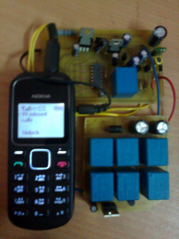
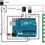
If you have sufficient prior knowledge of electronics, you should be making this complete unit within a days time. Let's begin the discussion. Basic Concept The idea here is to use an ordinary NOKIA 1280 cell phone as the modem attached permanently with a switching circuit. This entire unit now becomes the receiver unit.
The modem cell phone NOKIA1280 is assigned with desired numbers, for example the owners cell number and a few other numbers of the owners family members.
When the modem cell phone is called through these assigned numbers, the modem ring tone becomes active and this ring tone is applied to the control circuit and is processed for operating a relay and the connected load.
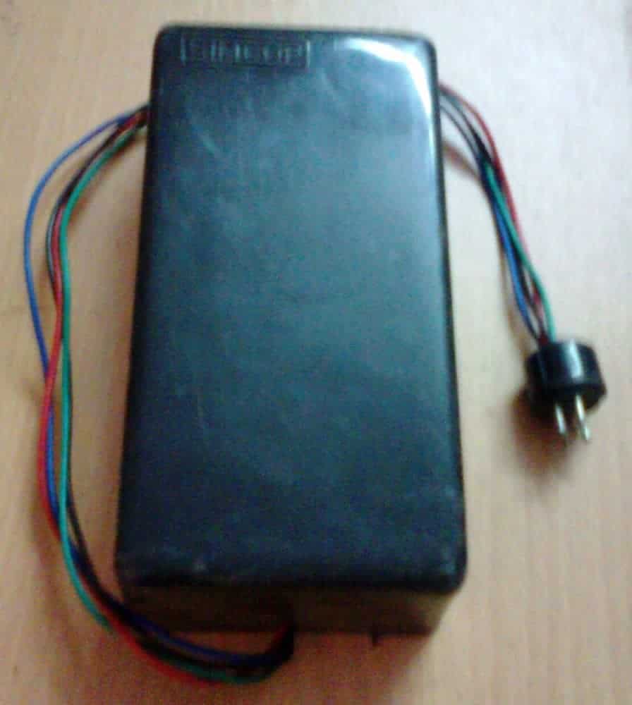
Since the modem cell phone needs to be attached permanently inside the switching unit, it needs to be charged at regular intervals so that it remains functional all the time.
For this, a separate cell phone charger module has also been incorporated along with the main circuit which keeps the modem cell phone battery always up to date and fully charged.
It is quite obvious that the attached cell phone modem will need a SIM card, which will need to be maintained as we do for normals cell phone operations.
I have explained the building process. You will have first get or procure the following materials or parts for making this unit. I would suggest not to make the Printed board initially, it would better to first test the working over a general board and if thing goes then you would want to transfer it over a well designed P-C-B.
Bill of Materials
All resistors are 1/4w 5% CFR unless otherwise stated.
- R1 = 22k
- R2 = 220 OHMS
- R3,R11,R12 = 100K R13 = 100 Ohms
- R4,R6,R7,R9 = 4.7K
- R5 = 1K,
- R8, R10 = 2.2M
- C1,C4,C5 = 0.22uF DISC TYPE
- C2,C3 = 100uF/25V
- T1,T2,T4,T5 = BC 547B
- T3 = BC557 B
- ALL DIODES = 1N4148 IC1 = 4093
- RL1, RL2 = RELAY 12V/300 OHMS SPDT
- JACK = 3.5mm AUDIO JACK
- CELL PHONE MODEM = NOKIA 1280
Circuit Diagram
Understanding the Schematic Diagram
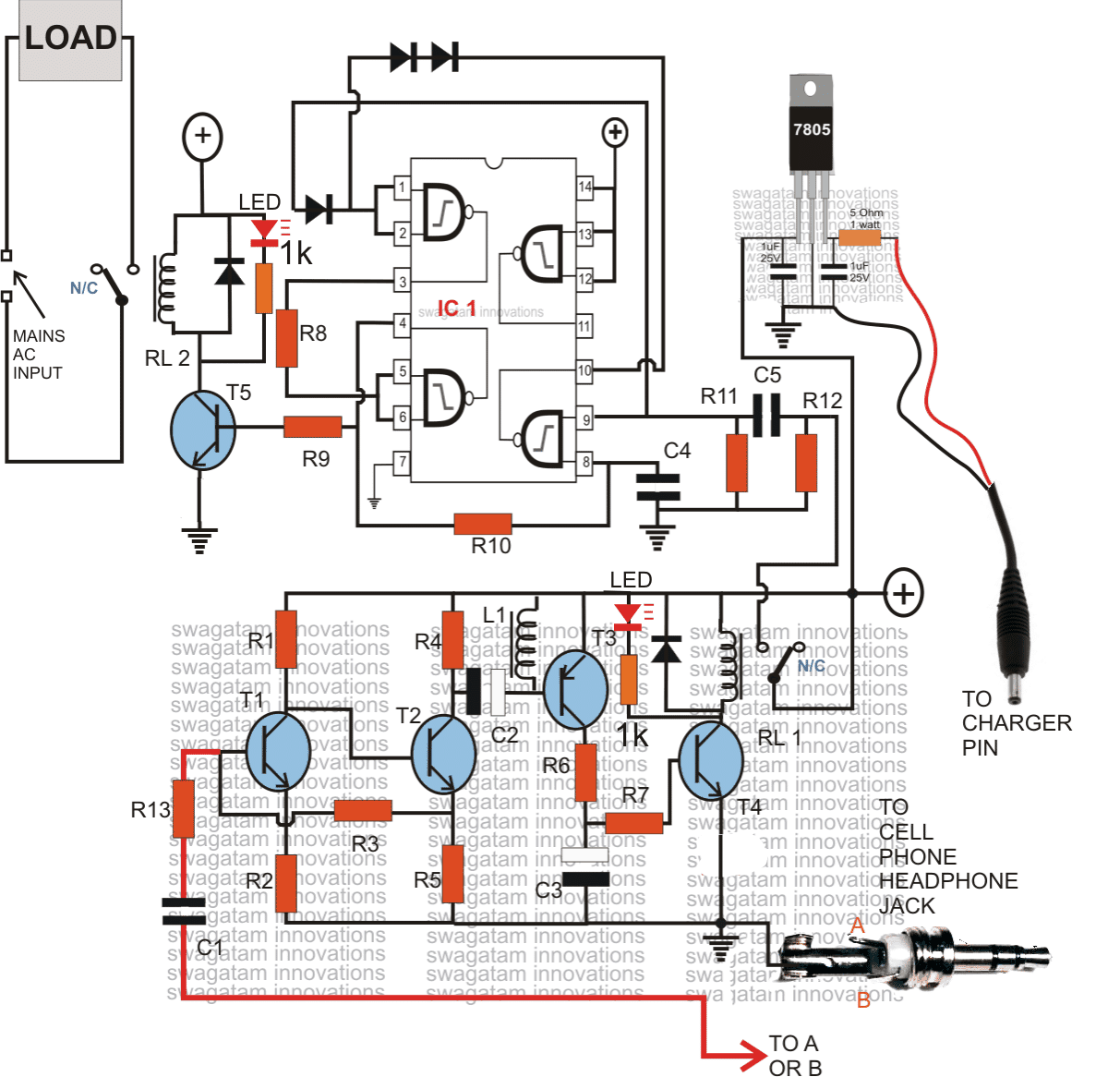
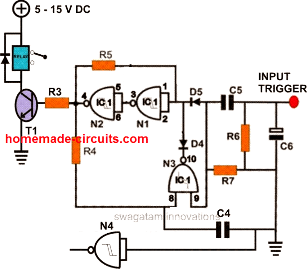
The above schematic of the proposed cellphone controlled remote circuit is rather very easy to understand. It may be divided into two main stages, the lower stage consisting of the transistors is a simple audio amplifier, the upper stage consisting of IC is the flip flop triggering stage.
When a signal is present at the 3.5mm jack, which might be the input ring-tone from the cell phone modem., T1, T2 amplifier to some greater level, which is further amplifier by T3, T4 to a level is becomes sufficient for triggering the relay RL1. RL1 instantly connects the supply to the input of the flip flop at C5, via its N/O contacts.
Note that RL1 will remain switched ON as long as the ring tone is present and will switch OFF the moment the ring tone or the signal over the 3.5mm jack is canceled. C3 makes sure that the relay does not get rattled by any insignificant signals or RFs.
L1 has been installed also for the same reason, that is for eliminating unwanted signals and making sure that T3, T4responds only to valid ring-tones.
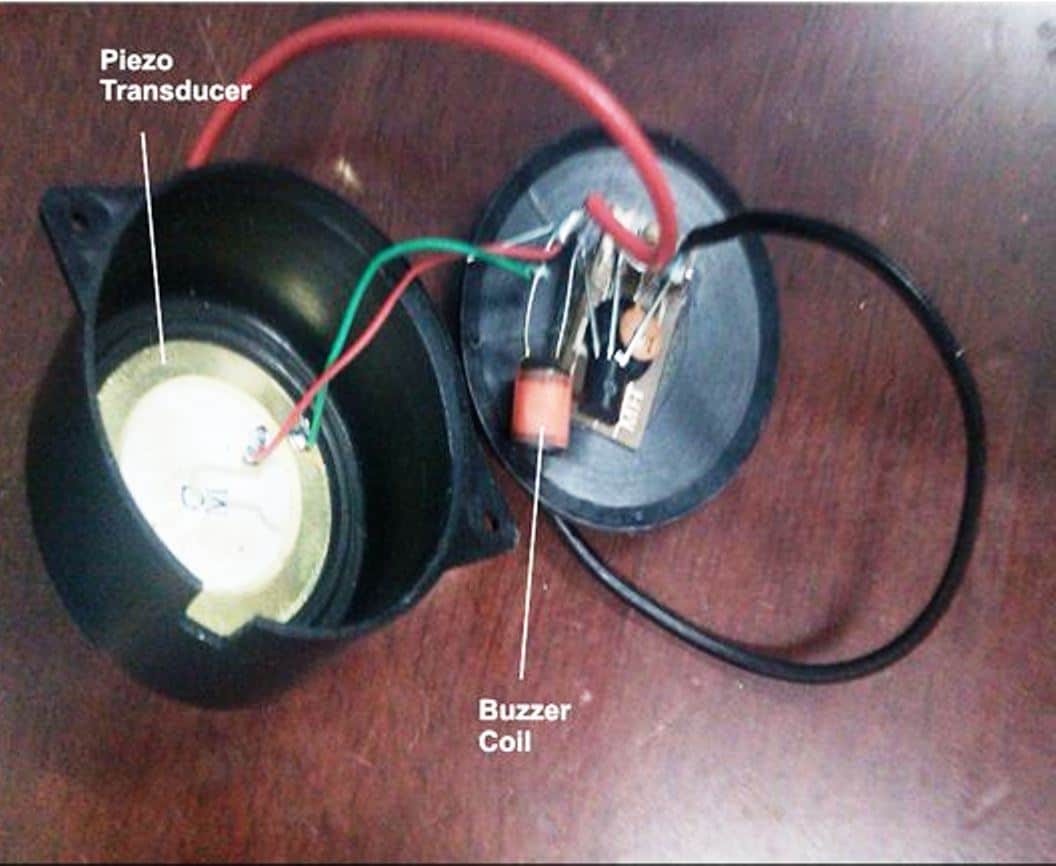
L1 is a buzzer coil, as used in piezo electric buzzers, or may be hand made by winding 1000 turns of 36SWG super enameled wire over a small ferrite core, size and shape does not matter. Image of L1, inside a buzzer
The period for which RL1 remains switched ON will have no consequence on the flip flop operation, the flip flop will switch ON and OFF in response to every subsequent missed call made from the owners cell phone.
The section comprising the IC 7805 is battery charger section, which needs to be connected to the battery charger input of the cell phone.
The charger will keep the cell phone battery always charged so that it remains functional all the time. The above circuit has been thoroughly tested and confirmed by me, so if you make everything as shown in the above diagram, it should start working immediately.
How to Assign Numbers Inside the MODEM CELL PHONE It's very easy. Just follow the following steps. Save the names and the numbers which are important and through which you want the above unit to be operated.
Next select a particular name-->--press scroll right-->--"contact details" will be displayed-->-- press options-->--scroll down-->-- select "assign tone"-->--select a ring tone which has a sustained, non-breaking tune-->-- do OK. Repeat this for all the desired numbers. Now go to settings, go to tone settings and select "empty", press OK.
That means now you have switched OFF the default ringtone and no ringtone will be audible for any numbers other than the above assigned ones.
So you can be rest assured that the system will not respond to wrong numbers or any unknown numbers. It will respond to only the calls made from the assigned numbers.
How to Power the Unit
The circuit needs to be powered through a DC12V/500mA or 1 Amp SMPS adapter.
The load may be any electrical appliance like lights, fans, AC, fridge or anything that you may like to switch using this system.
Video Clip showing the circuit functioning of the prototype
WARNING AND DISCLAIMER – THE PROPOSED DEVICE MUST BE USED FOR OPERATING ONLY THE COMMON HOUSEHOLD ELECTRICAL SYSTEMS AND PARAMETERS. THE PROPOSED CELL PHONE OPERATED SWITCH MUST NEVER BE USED FOR ANY OTHER INTENTIONS OR PURPOSE WHATSOEVER, AND THE AUTHOR TAKES NO RESPONSIBILITY FOR ANY LOSSES THAT MIGHT OCCUR IN CASE THE UNIT IS USED FOR OPERATING ANYTHING ELSE OTHER THAN WHAT'S BEEN SPECIFIED IN THE ABOVE ARTICLE.


Questions & Answers
https://www.homemade-circuits.com/wp-content/uploads/2011/12/4093-flip-flop-circuit.pn hello ji 1. Sir, the small ring of the cell phone turns on the relay due to which the load starts when the 4093 receives the trigger. I want the load on the long ring to be on, 2. Cellphones audio stage. If there is a lone time power cut, when the light comes on, the relay remains on for about 8-10 seconds until the capacitor gets discharged, if there is any solution, please suggest. thank you sir
Hello Mukesh,

The 4093 relay will be triggered ON, if the audio stage relay turns ON, so we have to stop the audio stage relay RL1.
I think you are using the following circuit:
Your first problem can be solved by adding a delay timer at the input.
For the second problem, please check whether the relay remains ON for 8 seconds when the mobile is connected with the audio stage or also when it is removed from the audio stage.
Please check this by first keeping the mobile phone connected, and then check again by keeping the mobile phone disconnected.
Sir, in this circuit 4093 is working fine and the circuit is also working but the voltage spike is not being controlled.
Secondly, I have made a cell phone based circuit 5 years ago and it was working well. Now due to a problem, I have to make another one. So there is no flaw in your circuit. Now I am facing problem in making the circuit. So I am expecting your help if you want. Thanks.
Mukesh, I completely understand your problem, and I will try my best to help you out.
However, protecting a CMOS based flip-flop circuit can be very difficult especially if the spikes are generated by a high power AC motor.
I am sure the spikes are being generated by your pump motor.
You can do one thing, please replace the R5 resistor with 100k and replace C6 with 470uF capacitor, and make sure you have a 1000uF/25V connected right across the supply terminals of the IC 4093, along with 0.1uF and 1N4148 diode.
Please check and let me know.
Sir in gsm cellphone circuit when trigger is given on C5 the relay turns on once and turns off immediately. I have made 5 boards, all have same problem, boards are separate, fixed 12v input supply, all components are new, IC is ok because it is working properly in your other circuit, I have installed 100uf/25v on pin 7 and 14, and C 0.1, 4148 perllel, still the relay does not stop on triggering, it turns off immediately. Please tell me a solution. Thank you
Hello Mukesh,
I have checked this circuit thoroughly in jeweler shop, motorcycle and car, for me it worked perfectly in all the occasions.
You said it is working OK in other circuit, which other circuit are you referring to?
Sir this circuit is working very well but when the light is switched on sometimes the relay gets on automatically and sometimes not, it is a separate circuit and a push switch has been installed, along with that 100uf or 0.1 have been added from the trigger point as in the circuit, input 12v/ 1amp. Full bridge rectifier plus filter 1000uf/25v, and supply has been given from IC7812.
…please note, 100uf or 0.1 must be connected across the supply terminals pin14 and pin7 of the IC…also add a 1N4148 across the supply line. Cathode to pin#14 and anode to pin#7.
Thank you Mukesh, for updating the results.
Actually, any circuit with CMOS ICs can be vulnerable to atmospheric noise interference (RF). IC 4093 is also a CMOS IC and therefore can be prone to RF disturbances.
Please try this: Supply the output from the 7812 to the 4093 through a 100 ohm resistor.
Also, Connect a 1N4148 diode in parallel with your 100uF or 0.1uF diode. Let’s see whether this helps to suppress the RF noise or not.
Make sure all the wire connections between the parts are as small as possible.
I hope you are not making it on a breadboard, because breadboard uses long wires, which can easily catch RF noises.
Sir, the 4093 board is made separately. I am touching the positive with a wire. The relay turns on once and turns off immediately. It does not stop. If a capacitor is connected between pin 1 and 4, then the relay works properly. Without connecting it, the relay does not stop. But on doing this, sometimes the relay turns on automatically when the light is switched on. This is a serious problem. The transistor and IC are OK. The board is also separate.
If the 4093 is getting activated by touching the positive line, that means something is wrong with your circuit or your power supply.
A capacitor between pin1 and pin4 is not required. Please try adding a 100uF capacitor directly across the +/- supply pins of the IC 4093 and also connect a 0.1uF directly across the supply pins of the IC.
Please refer to the following diagram and make sure all the components are connected correctly:
Let me know how it goes…..
Dear Sir, pls help.
Sir I made this circuit about 5 years ago which was working properly but a month ago I am facing a strange problem in which the relay led remains on permanently. Even after trying everything and reading all your comments the problem still persists. Then I made a new pcb in which on touching +ve with the wire the relay turns on once and turns off immediately. This had happened 5 years ago also for which I connected a c 224 or c 100uf 25v in parallel between pin number 1 and 4 of cd 4093 so that on coming of light the relay would turn on once and turn off immediately but the relay would not turn on unless it was rung. I have made a new board also same to same and it is working properly but the biggest problem I am facing is that when there is fluctuation in light the relay turns on automatically and the farm motor turns on and will not turn off unless it is turned off. Sorry sir I think there is a problem of ic 4093 in the circuit. Some part is missing between pin 1 or 4 because unless we add C 224 between pin 1 or 4 the relay will not turn on under any condition. Please the relay should not turn on automatically when there is light fluctuation and the relay should turn on when we turn it on without C 0.22 between pin 1 or 4 of CD4093.
Thanks
Hello Mukesh,

Thank you for your feedback and for testing this circuit.
If the input trigger relay is always ON, that means the transistor driver circuit has some problems, the 4093 is absolutely fine. The 4093 circuit cannot be faulty, you can check it separately using a push-button. Here’s the schematic of the 4093 circuit which has been verified by me thoroughly:
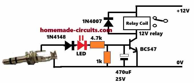
For the transistor relay driver circuit, please try the following circuit and let me know how it works. We can improve it until it works perfectly. Please first try and confirm this relay driver circuit separately, without connecting it with the 4093 circuit:
Please update me with your findings.
Hi, Mr Swagatam I have CD4027 IC with me how can i connect it to REPLACE CD4093 so to archieve this? Please help me!
Hi Bobtone, those two ICs cannot be replaced with each other.
I have several King Pigeon GSM relay boxes that I use to reboot devices when there is no Internet available. They have worked great until recently because of the move to 5G. They use GSM technology and are supposed to work with 4G but not in this country. Does your device/system work with the newer cell service?
The circuit explained in the above article uses the ringtone from a mobile phone for the required triggering. The mobile phone can use any SIM 4G or 5G that won’t matter as long as it is providing the ringtone to the detector circuit.
Do you sell a completed unit? Don dniebrugge
Sorry we don’t sell readymade kits
Please Sir, what modifications do you make to control more loads say about 5loads with 5 relays for home appliances.
You can connect more relays in parallel that will allow more loads to be connected in parallel
Interesting circuit! Do you have a value for L1? Looking to purchase a choke, rather than scavenging an innocent buzzer!
Glad you found it interesting. My inductance meter shows 48 mH for this coil, so anything between 40 and 100 mH would work nicely.
Hallo. I assembled all the parts as per the schematic. The lower part(amplifying circuit) works very well. The problem is with the flipflop circuit. When a call is made, both circuits goes on but the moment the call ends, both circuits goes off. Please assist as soon as possible.
Hello, you can isolate the flip flop section and check it separately to locate the fault. Please refer to the second design shown in the following article:
https://www.homemade-circuits.com/build-these-simple-flip-flop-circuits/
It is the same which is used in the cellphone design. Please ensure everything is connected as per this design, you can manually check the flip flop action by touching the input trigger point with the positive supply line, each alternate touching should make and break the relay operation. Once confirmed you may connect the input trigger with the RL1 contacts of the cellphone circuit for the final testing.
Thanks for the feedback. I connected the same but the only difference is that I never found a disc type capacitor of 0.22uf and instead I combined three 0.1uf ceramic capacitors in parallel. I also used a power supply adapter of 12v 3A. Can that be the problem?
I would also like to know which components are responsible for holding the two states.
That will also work, using 3nos 0.1uF instead of 0.22uF is fine. In the link which I referred previously you will be able to find the full explanation regarding the working of 4093 flip flop, it is a tested design. Actually it is C4 that is responsible for holding the two states, along with the gates N1/N2.
12V/3A is perfectly OK, in fact any voltage below 15V is fine, current is not relevant, it can be any value higher than 500mA. Make sure the relay coil resistance is not less than 200 ohms if the transistor is BC547
Please what IC did u use in the circuit and the voltage of the relay
Please Sir, could it be possible to control individual house hold appliances using this device?
And if possible, what are the possible modifications to be made?
No, you can control one device or many devices simultaneously but not individually…
IC is 4093, relay coil voltage will be as per the supply voltage, preferably 12V
Sir
The nokia phone with me is Model no. 101 Type RM769.
Is it suitable ?
Is it possible to on off more than one relay?
Mathew, I think it should work, however only a practical test can confirm this, yes you can apply more relays in parallel by appropriately upgrading the driver transistor
Please Sir, what to do incase you want control each appliance separately?
So that you could select those you want them to stay on, and off those you would not need at a particular time.
Hi Lawal, it is not possible with this design, you may have to search for an Arduino based design
Sir,
I want to control 5-6 different LEDs and motors via phone.
I mean one phone should e connected to the motors or LEDs and via other phone with help of any app I can switch to those LEDs. with any limit.
please heelp me sir..
Hi ankitesh,
you can try the following concept
https://www.homemade-circuits.com/dtmf-based-fm-remote-control-circuit/
in the first circuit remove the 5089 and the key pads instead feed the transmitter from your mobile earphone jack, and with DTMF app activated
Sir i have achieved the task but RL2 is making continue unwanted noice. What should i do ?
Isolate the upper 4093 circuit stage entirely by disconnecting it from RL1, and check it separately by manually by touching R12/C5 to the positive line, this should alternately switch RL2 ON/OFf, first check and confirm this.
Dear Sir,
Now i completed almost 90% task. The only problem is that relay RL2 activates with single time trigger pulse but deactivates with multiple time pulse. I think there is some residual current at output. What should I do ? Please help me sir.
Pushpendra, did you connect “C6” as advised by me earlier? If yes then now try connecting a resistor parallel to this capacitor..the value can be anywhere between 10K and 100K
Dear Sir,
Thanks a lot for immediate response. Sorry for frequent queries but I need your guide.
My part 2 sometime works. But the LED glows when I touch my body part like finger or thumb to rest part of PCB. I think it requires PCB to be grounded. But I made all connections as per above circuit. I have two seperate PCBs with IC CD4093 for same connection but same problem persists for both. I think there is continue supply on Pin 4 then LED continue glows by making finger connection to PCB.
There is a problem to use IC CD4013 because I lives in remote rural area so its not available easily. If I order this online then it will take more than a week to deliver so i can’t wait.
I hope to immediate response.
Pushpendra, if you compare the 4093 circuit from the other link I provided and the above 4093, you will find that a capacitor from the input trigger to ground is absent in the above design which might be causing instability, so you can add this capacitor and see the results.
see how C6 is added for stability in the 4093 design under this article:
https://www.homemade-circuits.com/2011/12/build-these-simple-flip-flop-circuits.html
Sir I tested 12 volt at C5 from N/O contact of RL1 but my LED across RL2 is continue glowing with vibration & sound in RL2.
That means you have done some mistake in the flip flop circuit.
you can refer to the following articles and do the required corrections or make a different flip flop design using IC 4013
https://www.homemade-circuits.com/2011/12/build-these-simple-flip-flop-circuits.html
https://www.homemade-circuits.com/2012/05/make-this-easiest-flip-flop-circuit.html
Sir i have made the circuit but i didn’t get result. would you like to help me on +919887095742. I Need urgent help.
Pushpendra, sorry a telephonic conservation won’t be possible, the above design is thoroughly tested by me but please note that it will require an experts knowledge to complete this project and is not recommended for newcomers, so please move ahead with caution,
The first relay goes on clicking and the secomd relay works only when the audio.jack is touched. And does this circuit only works with nokia phones. Please explain
Helo SwAGATAM the circuit works great with battery powered but when i use smps adapter 12v 1A it behave crazy and relay 2 switches on the connected load have failed to triubleshoot this i tried puting resistor on + of smps but failed please help me because i want to use that adapter than battery
Thanks Davis, if your relay is making noise, you can add a capacitor parallel with the relay coil
you can add more relays in parallel, but make sure the transistor is upgraded appropriately to handle the relay coil current