In this article I have explained how to make a 2 relay or two stage mains AC voltage stabilizer circuit for controlling and regulating 220V or 120V mains voltages through a simple circuit.
Introduction
In this power stabilizer circuit, one relay is wired to select the high or the low tap from the stabilizer transformer at some particular voltage level; whereas the second relay keeps the normal mains voltage switched in.
However, the moment there’s a voltage fluctuation it toggles and selects the appropriate HOT tap via the first relay contacts.
A simple power stabilizer circuit discussed here is very easy to build and yet is able to provide a 2-stage correction of the input mains.
A simple method of converting a normal transformer into a stabilizer transformer has also been discussed using circuit schematics.
Circuit Operation
As shown in the adjoining figure, the whole circuit operation can be understood with the following points:
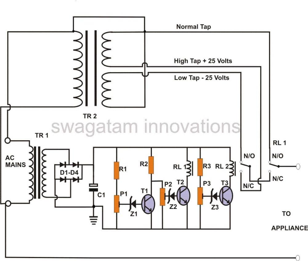
Basically the idea here is to make relay #1 switch at two different mains voltage extremes (high and low), which are considered not suitable for the appliances.
This switching enables this relay to select an appropriately conditioned voltage from another relay through its N/C contacts.
How to Wire the Relay Contacts
The contacts of this second relay #2 makes it sure that it selects a appropriate voltages from the stabilizer transformer and keeps it ready for the relay #1 whenever it toggles during dangerous voltage levels.
At normal voltages, relay #1 remains activated and selects the normal voltage through its N/O contacts.
Transistor T1 and T2 are used as voltage sensors. Relay #1 is connected to this configuration at the collector of T2.
As long as the voltage is normal, T1 stays switched off. Consequently T2 at this moment remains switched on. Relay #1 is activated, and its N/O contacts connect the NORMAL AC to the appliance.
If the voltage tends to rise, T1 slowly conducts, and at a certain level (decided by the setting of P1), T1 fully conducts and shuts off T2 and relay #1.
The relay immediately connects the corrected (lowered) voltage supplied by relay #2 through its N/C contacts to the output.
Now, in case of a low voltage T1 and T2 both will stop conducting, producing the same result as above.
However, this time the supplied voltage from relay #2 to relay #1 will be high, so that the output receives the required corrected level of voltage.
Relay #2 is energized by T3 at a particular voltage level (as per the setting of P3) in between the two voltage extremes.
Its contacts are wired to the stabilizer transformer tapping so that it selects the desired voltage appropriately.
How to Assemble the Circuit
The construction of this circuit is very simple. It may be done by with the following steps:
Cut a small piece of a general purpose board (about 10 by 5 mm).
Begin the construction by inserting the transistors first, keeping ample space between them so that the other can be accommodated around each of them. Solder and cut off their leads.
Next, insert the rest of the components and interlink them with each other and the transistors by soldering. Take the help of the circuit schematic for their proper orientations and placements.
Finally, fix the relays to complete the board assembly.
The next page deals with the construction of the power stabilizer transformer and the testing procedure. After these procedures are completed, you may integrate the tested circuit assembly to the appropriate transformers.
The whole set up then may be housed inside a tough metal enclosure and installed for the desired operations.
Parts List
- R1, R2, R3 = 1K, 1/4W,
- P1, P2,P3 = 10K, LINEAR PRESETS,
- C1 = 1000uF/25V
- Z1, Z2, Z3 = 3V, 400mW ZENER DIODE,
- T1, T2,T3 = BC 547B,
- RL1, RL2= RELAY 12V,SPDT,400 OHMS,
- D1--D4 =1N4007,
- TR1 =0-12V, 500mA,
- TR2 = 25- 0 - 25 VOLTS, 5 AMPS. WITH SPLIT CENTER TAP,GENERAL PCB,METALLIC ENCLOSURE, MAINS CORD, SOCKET, FUSE HOLDER ETC
How to Convert an Ordinary Transformer into a Stabilizer Transformer
Stabilizer transformers are normally made to order and are not available ready made in the market.
Since multiple mains AC voltage taps (high and low) outputs are required from them and also since these are specific for a particular application, it becomes much difficult to procure them ready made.
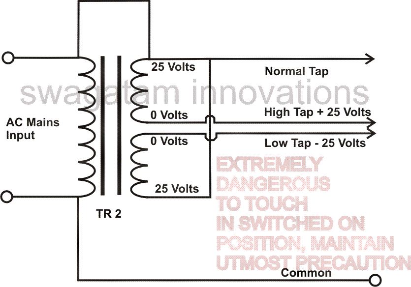
The present circuit also needs a power regulator transformer, but for the ease of construction a simple method may be incorporated to convert an ordinary power supply transformer into a voltage stabilizer transformer.
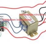
As shown in the figure, here we require a normal transformer rated at 25-0-25/ 5 Amp.
The center tap should be split, so that the secondary may consist of two separate windings. Now it’s just a matter of connecting the primary wires to the two secondary windings as shown in the diagram.
Thus, by following the above procedure, you should be able to successfully convert an ordinary transformer into a stabilizer transformer, very handy for the present application.
How to Set Up the Unit
You will require a variable 0-24V/500mA power supply for the set up procedure. It may be completed with the following steps:
Since we know that the AC mains voltages fluctuations will always create a proportionate magnitude of the DC voltage fluctuations from a transformer, we may assume that for input voltages of 210, 230 and 250, the correspondingly obtained equivalent DC voltages should be 11.5, 12.5 and 13.5 respectively.
Now the setting of the relevant presets becomes very simple as per the above voltage levels.
- Initially keep the both the transformers TR1 and TR2 disconnected from the circuit.
- Keep the slider of P1, P2, and P3 at somewhere around midway position.
- Connect the external variable power supply to the circuit. Adjust the voltage to about 12.5.
- Now slowly start adjusting P3 until RL2 just activates.
- Decrease the supply voltage to about 11.5 volts (RL2 should deactivate in the course), adjust P1 so that RL1 just deactivates.
- Gradually increase the supply to about 13.5 – this should make RL1 and RL2 to energize one after the other, indicating the correctness of the above settings.
- Now slowly adjust P2 so that RL1 again deactivates at this voltage (13.5).
- Confirm the above settings by varying the input voltage from 11.5 to 13.5 back and forth. You should get the following results:
- RL1 should deactivate at 11.5 and 13.5 voltage levels, but should remain activated in between these voltages. RL2 should switch ON above 12.5 and switch off below 12 volts.
The setting procedure is now complete.
The final construction of this power regulator unit may be concluded by connecting the tested circuit with the relevant transformers and concealing the whole section inside a well ventilated metallic enclosure as suggested in the previous page.
Comments
THANKS FOR THIS GREAT LECTURE. NOW MY QUESTION IS THIS; FROM THE CONFIGURATION PROVIDED ASSUMING THAT THE STABILIZER IS REQUIRED WORKING WHEN AC MAINS DROPS TO 160VOLTS HOW DO WE SET UP THE PRESET. I HOPE THAT IS REALLY POSSIBLE FOR THE CIRCUIT PROVIDED AND THE TRANSFORMER RATINGS. THANKS!
Glad you liked it, you will have to carefully adjust the preset 3 so that it switches OFF RL2 at 180V, adjust preset 2 so that it switches OFF RL1 at 170V
Will the stabilizer gives accurate output voltage (like 220 V ) or output voltage of certain range (like 215-230 V) of varying input voltage
It will not give exact 220V, rather within a certain range
hello sir . i build this circuit and it works. but during setting up the first step at 12.5 volts worked ,while adjusting p3 relay 2 activated at 11.5 relay 1 deactivated also. adjusting power from 11.5-13.5 activated both relays simultaneously. now the problem is,at 13.5 relay1 remain activated . i adjusted p2 end to end no change . how ever at lower volts say 11.8 p2 deactivated relay1 but is not working at the right place 13.5 . please can u assist me rectify the problem?
USA, while adjusting the power supply pot the voltage could rise or fall abruptly due to pot inefficiency and hand inaccuracy and this could produce random relay activation.
you must adjust the pot very very slowly and skillfully to actually see the relay sequence in the correct way.
connect LEDs in series with each of the transistor emitters, this will help you to see the changeovers visually.
the circuit is too straightforward and I don't think it needs much explanation or any critical troubleshooting.
Hi Sir,
can this stabilizer be connected to the main house power source, I main can I use it to the whole house, sorry if my question seems stupid but I'm very new to power circuits
thanks
Hi ayman,
for a 15000+ watt load the relay contact must be rated at above 100 amps…so 10amp is out of question…it's nowhere near.
TR2 is the one which need to be upgraded…and it should be rated at around 20,000 watts to safely handle 15000 watt load.
Hi Swagatam,
The house total wattage load = 15499/220 * 2 =140.9
the relay I have 7A 250VAC | 10A 125VAC
12A 120VAC | 10A 28VDC
(what should be mentioned on the relay that I have to use )??
which transformer I should upgrade TR1 or TR2 (the transformers I have TR1 = 0-12V, 500mA, TR2 = 24 – 0 – 24 VOLTS, 5 AMPS
( what I should use)??
Sorry for asking many questions but I hope to build a perfect stabilizer with your help
thanks and regards
Hi Ayman,
divide the total wattage of the loads with 220, and multiply the result with 2…that will provide you the required relay contact rating, the transformer wattage will need to be twice that of the total wattage of the load
Hi Swagatam,
Thank you for your reply and for the efforts you do to help us Improve our hobby
what do you advice for the upgraded relay and transformer (the house is 220V, and I have Air condition, two refrigerators, 3 TV's , 2 water heaters , 2 electric ovens) this is all the appliances in my house, please suggest what is the relay and transformer proper wattage I should use
thanks
Hi ayman,
yes it can be used for a house or even for the entire building, the circuit just needs to be upgraded accordingly.
The relay and the transformer needs to be upgraded with appropriate wattage rating so that it can safely handle the connected load current
Your description: "…..T1 fully conducts and shuts off T1 and relay #1."
I think it should be: "…..T1 fully conducts and shuts off T2 and relay #1."
Regards,
Don
OK thanks, I'll correct the typo soon.
plz send 4-relay stabilizer circuit with delay timer if possible ,regards.
ch wazir.
try the following circuit, use only 4 stages out of the shown 7 stages:
https://www.homemade-circuits.com/2011/12/how-to-make-accurate-7-stage-op-amp.html
I think the best thing is to disconnect the relay and IC part of the circuit and run ac mains through the input part of TR1 and then read the dc through bridge rectifier and smoothing capacitor network. The dc voltage recorded at a given ac mains voltage value can now be used as reference instead of assuming that 210acv produces 11.5dcv. Is it conventional to assume.
yes that’s correct!
yes surely you can, Oliver
Hi Swagatam,
now i can use my contactors… thank you very much.
Regards,
Oliver
Hi Oliver, yes only a transformer would sufficient for your requirement, wire it up as shown in the second diagram.
Hi Swagatam,
only the trafo without the circuit will do?
Thanks,
Oliver
Hi Oliver,
you need an approximately fixed and constant 200V for your contactor unit, right?
So you would need only a transformer wired accordingly for getting the required 200V output, as given in the second design.
In the second design, the lower section could be used for your application.
Actually, since you require a step down voltage only, the upper 0-25V winding becomes meaningless, so may be only a 0-25V transformer could be just enough.
Hi Swagatam,
How can i use this to my 200V contactor? how will i adjust the voltage?
for TR1… can i use transformerless power supply?
can i use 24-0-24 for TR2?
Regards,
Oliver
Decrease the supply voltage to about 11.5 volts (RL2 should deactivate in the course), adjust P1 so that RL1 just deactivates.
I copied this from your guide in the above circuit. I thought should be adjust p1 so that RL1 activates at 11.5 since it represents the 210acv. Because the referenced statement has it that RL1 gets deactivated when P1 is adjusted at 11.5v dc supply as if it was previously activated before then. Thanks.
The circuit above and the transformer configuration is very comprehensive. My question is in transformers with multiple tappings, 170,190, 210, 230,250 volts and two auxiliary tapings; 0 – 18v, 0 – 18v each. How can the transformer be configured to get the buck and boost effect expected of the stabilizer. I have seen a lot of stabilizers with only a single transformer and so I begin to wonder how the configuration is done to create that effect.
In stabilizers with multiple tap transformer, opamps are used to detect the rising or falling voltage levels and in response it activates relays that switch ON the higher voltage taps sequentially when the voltage drops, and when the voltage rises, the lower voltage taps are activated by the respective relays. You can see an example of this type of stabilizer in the following article:
5 KVA to 10 KVA Automatic Voltage Stabilizer – 220 Volts, 120 Volts
Yea! After going through your article on the working of opamps using 741 as a case study I now know how such setup is done. Am grateful.
You are welcome Moses!