In this project, I have explained how to control motor speed using Arduino PWM circuit, and how to implement reverse forward or direction control in a DC motor using Arduino through a couple of push button switches. Any high current motor upto 30 amp can be controlled using this set up.
Introduction
Motor is a very essential component in electrical and electronics as they are used as actuators in many areas.
We need motors for small applications like robotics as well as in areas where heavy motors are used (industries etc.).
Now motors which are used for small applications can be controlled easily as they do not take much current(less than 2amp).
And these motors can be easily controlled by using microcontroller like arduino with motor driver ic’s like L298 or L293D.
But motors which are used for heavy purposes (greater than 10amp), cannot be controlled using these ic’s as they can supply limited current ( max 2amp). So how these motors are controlled than?
The answer is simple: using Relays, which acts as switches i.e. switch large current using small current. In this way two things can be achieved:
1. Running our high current motor itself.
2. Isolating the circuit, thus preventing any shocks.
Now any microcontroller can be used to switch these relay. We will be using arduino UNO here.
COMPONENTS REQUIRED FOR THIS PROJECT:
1. ARDUINO UNO: to give input logics to relay’s primary side.
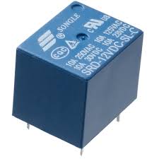
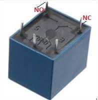
2. SPDT RELAY -2: two relays are required for rotation in both directions. Contacts must be rated to handle the high current motor specifications:
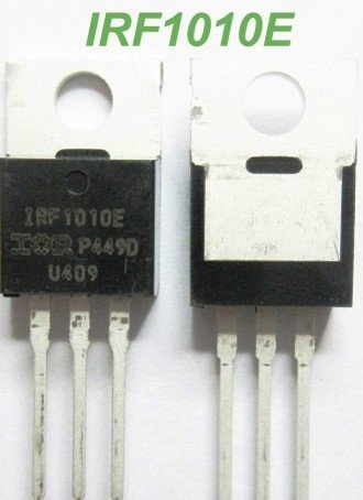
3) Power Mosfet: You can use IRF1010 mosfet
4. BATTERY (12v) : to supply power to motor.
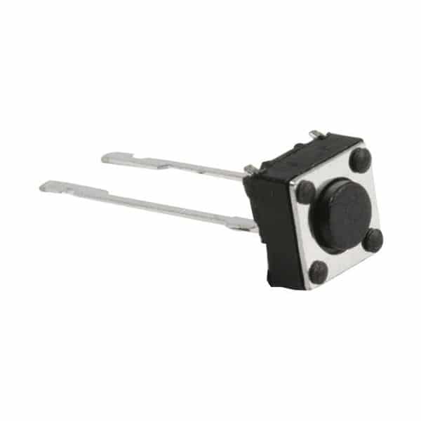
5. TWO PUSHBUTTONS: to give inputs to arduino (i.e. when pressed and when not pressed)
6. TWO 10K RESISTORS: for debouncing (I have explained below)
7. CONNECTING WIRES: for making connections.
SCHEMATIC AND CONSTRUCTION:
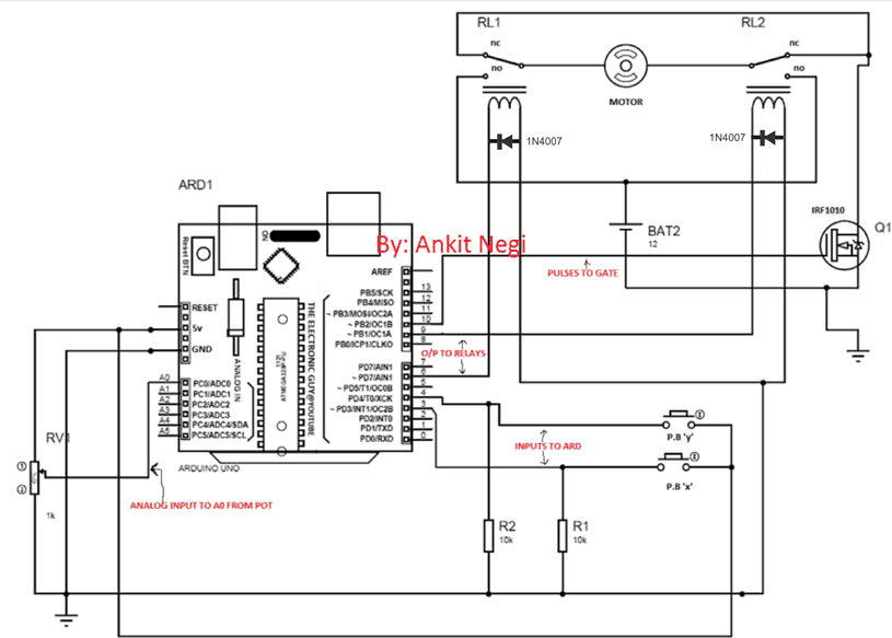
Make connections as shown in the figure.
1. Connect normally open terminal of both relay to positive terminal of battery and normally closed terminal to battery’s negative terminal.
2. Connect the motor in between the remaining terminal (out of three) of each relay.
3. Connect one terminal of primary side of relays to the output pins of arduino as specified in the code and other terminal to ground.
4. Connect one terminal of both pushbuttons to 5v pin of arduino and other terminal to input pins as specified in the code.
4. **Don’t forget to connect resistors as they are very important for proper functioning of this circuit, as I have explained below:
WHY RESISTORS ARE CONNECTED?
You may find that there's nothing at all connected to input pins of Arduino, but that does not mean these pinouts may be a logical zero when the indicated switch is open
Rather it implies that when switch is open arduino can take any random value between logic 0 and logic 1, which is not good at all (this is called bouncing).
So what we want here is that when nothing is connected to the input pin i.e. pushbutton is open, arduino takes 0 input from the pin.
And to achieve this, the pin is directly connected to ground before the pushbutton via resistor.
If it is directly connected to ground without resistor there are good chances that it will burn out as pin will be shorted to ground and huge amount of current will flow. To prevent this, a resistor is connected in between.
This resistor is called pulldown resistor as it is pulling logic on pin to 0. And this process is called debouncing.
CODE:
Burn this code into your arduino.
// ---------------- Variable Declarations ----------------
int x;   // Input from pin 3
int y;   // Input from pin 4
int z;   // Potentiometer ADC value
int w;   // Mapped PWM value

void setup() {

  pinMode(6, OUTPUT);    // RL1 control
  pinMode(9, OUTPUT);    // RL2 control

  pinMode(3, INPUT);     // Direction input 1
  pinMode(4, INPUT);     // Direction input 2

  pinMode(10, OUTPUT);   // PWM output to MOSFET gate
  pinMode(A0, INPUT);    // Potentiometer input

  Serial.begin(9600);
}

void loop() {

  // -------- PWM Speed Control --------
  z = analogRead(A0);              // Read potentiometer
  w = map(z, 0, 1023, 0, 255);      // Map ADC to PWM range

  analogWrite(10, w);              // Apply PWM to MOSFET
  delay(1);

  // -------- Serial Monitoring --------
  Serial.println(z);
  Serial.println(w);

  // -------- Direction Control --------
  x = digitalRead(3);
  y = digitalRead(4);

  if (x == 0 && y == 0) {           // Halt motor
    digitalWrite(6, LOW);
    digitalWrite(9, LOW);
  }

  if (x == 1 && y == 0) {           // Clockwise rotation
    digitalWrite(6, HIGH);
    digitalWrite(9, LOW);
  }

  if (x == 0 && y == 1) {           // Anticlockwise rotation
    digitalWrite(6, LOW);
    digitalWrite(9, HIGH);
  }

  if (x == 1 && y == 1) {           // Halt motor
    digitalWrite(6, LOW);
    digitalWrite(9, LOW);
  }
}
Working (understanding code):
• DIRECTION CONTROL:
A. When both pushbuttons are not pressed:
In this condition, arduino takes 0 input from both the pins. As specified in the code in this condition both the output pins give 0 logic (LOW) :
if(x==0 && y==0){digitalWrite(6,LOW);
digitalWrite(9,LOW);}
Since input voltage to primary of both the relays is zero secondary terminal of both remains at normally closed position. Thus there is zero volts at both terminals of motor, causing no rotation.
B. When push button X is pressed but Y is not pressed:
In this condition, arduino takes 0 inputs from pin 4 but input1 from pin3. As specified in the code in this condition pin 6 should be at logic 1(HIGH) whereas pin 9 at logic 0(LOW) :
if(x==1 && y==0){digitalWrite(6,HIGH);
digitalWrite(9,LOW);}
Since input voltage to relay#1 is high, the switch of this relay is thrown to normally open condition whereas input voltage to relay 2 is low, the switch of this relay remains in normally closed condition causing 12v and 0v respectively across motor terminals, causing rotation of motor in one direction.
C. When push button Y is pressed but X is not pressed:
In this condition, arduino takes 1 input from pin 4 but input0 from pin3. As specified in the code in this condition pin 6 should be at logic 0(LOW) whereas pin 9 at logic 1(HIGH) :
if(x==1 && y==0){digitalWrite(6,LOW);
digitalWrite(9,HIGH);}
Since input voltage to relay#2 is high this time, the switch of this relay is thrown to normally open condition whereas input voltage to relay#1 is low, the switch of this relay remains in normally closed condition causing 12v and 0v respectively across motor terminals, causing rotation of motor in another direction.
D. When both pushbuttons are pressed:
In this condition, arduino takes 1 input from both the pins. As specified in the code in this condition both the output pins give 0 logic (LOW):
if(x==0 && y==0){digitalWrite(6,LOW);
digitalWrite(9,LOW);}
Since input voltage to primary of both the relays is zero secondary terminal of both remains at normally closed position. Thus there is zero volt at both terminals of motor, causing no rotation.
• SPEED CONTROL:
Let’s say potentiometer is at such position when it gives 0 volts as input to the A0 pin of arduino. Due to this, arduino maps this value as 0 and thus gives 0 as output PWM on pin#10 i.e.,
analogWrite(10,0);// write the mapped value to 10th pin as output
Hence gate of mosfet gets 0 current due to which it remains off and motor is in the switched OFF position.
However, as the pot is rotated and the value of the pot is varied, voltage on pin A0 also varies, and this value is mapped on pin#10 with a proportionately increasing PWM width, causing more current to flow through the motor and the mosfet drain, which in turn allows the motor to gain more speed proportionately, and the same happens vice versa.
Thus from the above discussion we can see how an Arduino can be used for controlling the speed as well as direction (reverse forward) of a high current DC motor simply by adjusting the specified pot and through couple of push buttons.
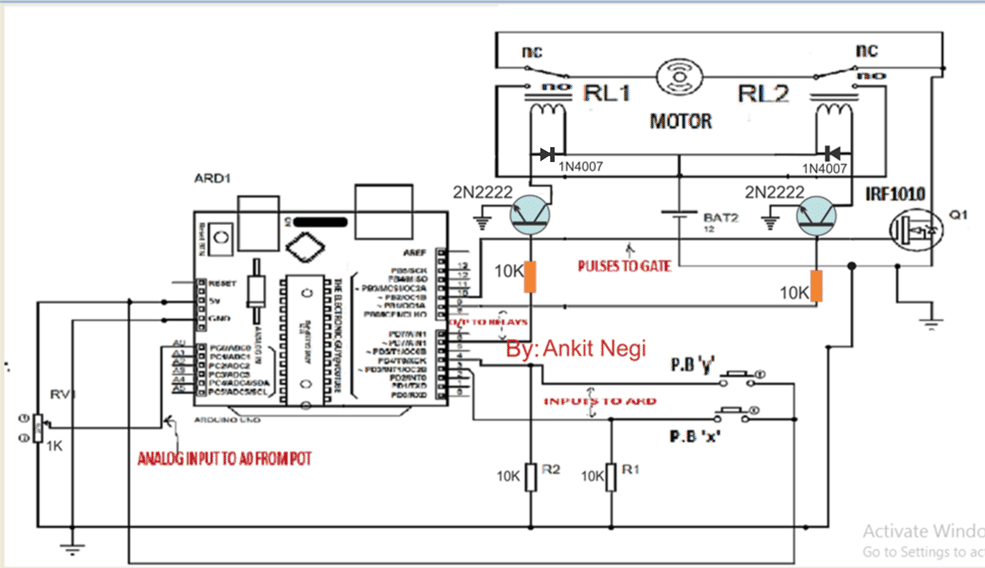
Update: For high current motor, please use 12V/30 amp relays and BJT driver stages for operating these high power relays as indicated in the following modified diagram:


Comments
BLDC controller using Microcontroller
Good day Mr. Swagatam.
Is it posible to develope a New circuit for research purposes in the magnetic & frequency invironment working in the same priciples as this project.
ie……
a Very warm greeting to all.
As a very NEW researcher in magnetic & frequency energy, with very little electronic board developing experience, I need the help of people who KNOWS in the Arduino Forum.
Can someone please help develope a BLDC PWM sensless Motor Controller that I can change all input manually for research purposes.
What I need is a PCBoard combination of the motor power driver & the Frequency Driver with all protections ie. BEMF, current and what is needed for protection on the board.
Also what will be a winner with the LCD monitor inluded with all of the INPUTS:
1. V – A – Freq – RPM – Heat in Celcius
OUTPUT:
1. V – A – Freq – Heat in Celcius
The input power 200 – 240VAC rectified to DC PWM Power driver and the volts VARIABLE from 0V – 240VDC with the Board fitted with (LCD) and knobs changeable in 12VDC intervals and at least 10A circuitry with protection build in.
The Freq board combined to the power driver where the Duty Cycle & the Frequencies is variable seperately not effecting each other in the settings from 1% – 99%. drive frequencies into the power IGBT to the driver coils.
The Frequency settings from 1Hz – 16Mhz with 10Hz interchangeable settings for certain
range of frequencies. (Mega 2560 & Uno Ref 3).. Maybe the coding will control the manual settings…. I am not sure with a lack of knowledge.
This Bridge High Power High Torque Power driver must be controlled either by the Arduino Mega 2560 and/or Uno Ref 3, with a JUMPER setting on the Power Board to change the board output settings from single phase to 3 phase outputs and visa versa.
I presume that the only difference will be the coding and pin relationships to each other of the Arduino boards.
At last but not the least, is all the connections diagram of the Combined Power Driver & Freg Driver board onto the Arduino Mega 2560 and/or Uno ref 3
Attached link with more details of one of these drivers and circuit.
BLDC sensorless Motor Controller & Frequency drive.
https://simple-circuit.com/pic18f4550-esc-sensorless-bldc-motor-controller/
Hope you people out there can support and help me with this research project by develope a new bord schematic that I may receive in a GERBER file for building the new boards.
Looking forward to hear from anybody who are prepare to help.
I will gratefully accept circuit diagrams in Gerber file for manufacturing.
Warm Greetings & Blessings from out the Lovely South Africa.
Gert.
Thank you Messenger for this inquiry, I’ll forward this question to our Arduino expert Mr. GR, if possible we may try to present the idea in a new article.
Thanks so much Swag.
Most appreciate.
you are welcome!
Wonderful project, thumbs up.
Can I remove the Arduino IC and solder it on a breadboard after programming it?
thanks, glad you liked it!
yes you can solder it separately on a breadboard
https://www.homemade-circuits.com/make-arduino-breadboard/
Circuit seems to violate the #1 rule of relays: *always put a diode in parallel with the coil, cathode to positive. If you don't, you risk damage to the relay driver.
Thanks for pointing it out, I have corrected diagrams.
you will have to use high power mosfets to derive motor coils on and off in a sequential manner.Each mosfet will be triggered by microcontroller one by one so that rotor can rotate.
you can use the same code to triggger it:
digitalWrite(pin,HIGH)
delay(how fast coil should energized)
digitalWrite(another pin,High) but make sure when one pin is high all other must be low
In this way you can drive the motor.
I hope this helped
Dear Ankit , could you please suggest a BLDC motor driving circuit based on micro controller for a 12/24 volt 4o inch ceiling fan.
Regards:
Krishna Kaushik