• Skip to main content
  • Skip to primary sidebar

Homemade Circuit Projects

Need circuit help? Post them in the comments! I've answered over 50,000!

Blog | Categories | About | Contact | Calculators-online
You are here: Home / Arduino Projects / Fading an LED ON/OFF – Arduino Basics

Fading an LED ON/OFF – Arduino Basics

Last Updated on December 5, 2024 by Swagatam 2 Comments

In this post I have explained a basic Arduino function where I have explained the process of fading an LED ON/OFF through some basic code implementations.

Creating a Fading Effect

We see how to use an analogwrite() function in order to implement a fading ON/OFF of an LED. The function incorporates PWM pulses across a pinout for accomplishing the suggested fading action over the connected LED.

Hardware Needed

Along with your Arduino, other materials such as a breadboard, an LED and a 220 ohm, 1/4 wat resistor would be required for the experiment.
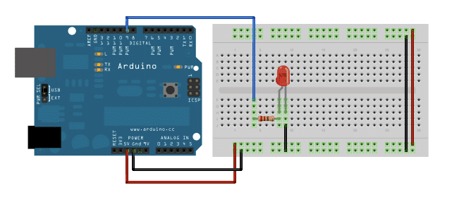
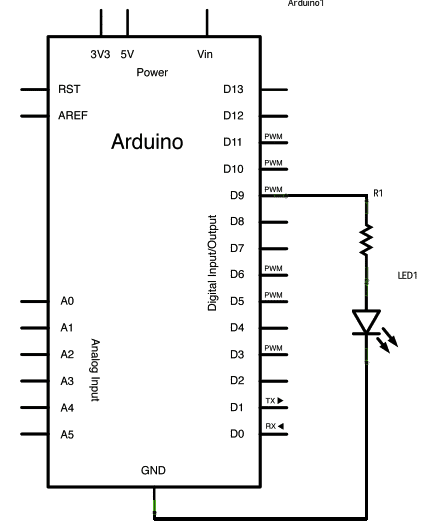
The Circuit

The steps involved for the proposed LED ON/OFF fading with an Arduino are as follows:

1. Attach the longer terminal of the LED to the digital output pin#9 via the 220 ohm resistor in series, while the cathode or the shorter terminal of the LED with the ground directly or the negative supply rail.

Arduino fade
simple afding arduino

The Code

Once pin#9 of the board is integrated as the LED positive pin, the setup() function could be simply left alone and would'nt need any further operations.

The main loop code component in the form of analogwrite() needs a couple of acknowledgments: The first being addressing the function regarding which pin to be used for writing, and the second being the value of the PWM to be determined.

For initiating a fading ON/OFF effect on the connected LED, the PWM could be consistently varied from zero to maximum or to 255 and vice versa, completing the entire single cycle of operation.

The code below shows the PWM magnitude being determined through a variable named as brightness. Also the it increments by variable fadeAmount in the loop.

In a situation where brightness is at the extreme values (either 0 or 255), prompts fade

amount to become negative.

Meaning if suppose the fadeAmount is 5, it changes to -5, and 5 in case it's set a 55. In the later periods in the loop these changes results brightness to vary course of the action as well.

The function analoguewrite() causes quick alterations in the PWM values, such that the delay at the conclusion of the sketch controls the fading speed.
You may experiment with the delay values to investigate the changes produced in the program.
/*
Fade

This example shows how to fade an LED on pin 9
using the analogWrite() function.

This example code is in the public domain.
*/

int led = 9;           // the pin that the LED is attached to
int brightness = 0;    // how bright the LED is
int fadeAmount = 5;    // how many points to fade the LED by

// the setup routine runs once when you press reset:
void setup()  {
// declare pin 9 to be an output:
pinMode(led, OUTPUT);
}

// the loop routine runs over and over again forever:
void loop()  {
// set the brightness of pin 9:
analogWrite(led, brightness);

// change the brightness for next time through the loop:
brightness = brightness + fadeAmount;

// reverse the direction of the fading at the ends of the fade:
if (brightness == 0 || brightness == 255) {
fadeAmount = -fadeAmount ;
}
// wait for 30 milliseconds to see the dimming effect
delay(30);
}

You'll also like:

  • 1.  Electronic Candle Flame Simulator Circuit
  • 2.  How to Interface 4×4 Keypad with Arduino
  • 3.  Compatible LED Tube Light Circuit for Standard Ballast Fixtures
  • 4.  Transformerless Automatic Night Lamp Circuit
  • 5.  220V Dual Alternate Lamp Flasher Circuit
  • 6.  Underwater LED Boost Converter Circuit with Dimmer

About Swagatam

I am an electronics engineer with over 15 years of hands-on experience. I am passionate about inventing, designing electronic circuits and PCBs, and helping hobbyists bring their projects to life. That is why I founded homemade-circuits.com, a website where I share innovative circuit ideas and tutorials. Have a circuit related question? Leave a comment.... I guarantee a reply!

Previous Post: « 110V Compact LED Tubelight Circuit
Next Post: High Voltage, High Current Transistor TIP150/TIP151/TIP152 Datasheet »

Reader Interactions

Comments

  1. Blitz Tear says

    August 20, 2014 at 4:45 pm

    Good Day Mr. Majumdar. We were hoping if you could give us tips on how to build a 8×8 dot matrix with RGB leds. For our project. We have MPLABX IDE v1.85 for C language, PICkit2 as emulator. Looking to use PIC12Fxxx or PIC16Fxxx IC's. We wanna use only Red-Green-Blue colors to display desired characters. We really have nothing to start with. I mean, what IC do we use? what other components do we need? Hoping for your reply. Thank You in advance.

    Reply
    • Swagatam says

      August 21, 2014 at 5:11 am

      Good day Blitz, frankly speaking, I am not expert with MCU circuits and stuffs, so I am as blank as you are right now, hopefully soon I'll get this field too in my area of expertise.

      Reply

Need Help? Please Leave a Comment! We value your input—Kindly keep it relevant to the above topic! Cancel reply

Your email address will not be published. Required fields are marked *

Primary Sidebar

Subscribe to New Circuit Ideas

Categories

  • Arduino Projects (87)
  • Audio and Amplifier Projects (132)
  • Automation Projects (17)
  • Automobile Electronics (101)
  • Battery Charger Circuits (82)
  • Datasheets and Components (102)
  • Electronics Theory (143)
  • Free Energy (37)
  • Games and Sports Projects (11)
  • Grid and 3-Phase (19)
  • Health related Projects (25)
  • Home Electrical Circuits (12)
  • Indicator Circuits (14)
  • Inverter Circuits (87)
  • Lamps and Lights (142)
  • Meters and Testers (69)
  • Mini Projects (46)
  • Motor Controller (64)
  • Oscillator Circuits (27)
  • Pets and Pests (15)
  • Power Supply Circuits (108)
  • Remote Control Circuits (50)
  • Security and Alarm (64)
  • Sensors and Detectors (100)
  • Solar Controller Circuits (59)
  • Temperature Controllers (42)
  • Timer and Delay Relay (49)
  • Transmitter Circuits (29)
  • Voltage Control and Protection (37)
  • Water Controller (36)

Calculators

  • Battery Back up Time Calculator
  • Capacitance Reactance Calculator
  • IC 555 Astable Calculator
  • IC 555 Monostable Calculator
  • Inductance Calculator
  • LC Resonance Calculator
  • LM317, LM338, LM396 Calculator
  • Ohm’s Law Calculator
  • Phase Angle Phase Shift Calculator
  • Power Factor (PF) Calculator
  • Reactance Calculator
  • Transistor Astable Calculator
  • Transistor base Resistor Calculator
  • Voltage Divider Calculator
  • Wire Current Calculator
  • Zener Diode Calculator
  • Filter Capacitor Calculator
  • Buck Converter Calculator
  • Boost Converter Calculator
  • Solar Panel, Inverter, Battery Calculator
  • Wire Current Calculator
  • SMPS Transformer Calculator
  • IC SG3525, SG3524 Calculator
  • Inverter LC Filter Calculator

People Also Search

555 Circuits | 741 Circuits | LM324 Circuits | LM338 Circuits | 4017 Circuits | Ultrasonic Projects | SMPS Projects | Christmas Projects | MOSFETs | Radio Circuits | Laser Circuits | PIR Projects |

Recent Comments

  • Swagatam on Simple Delay Timer Circuits Explained
  • Swagatam on The Role of Inductor Coil in SMPS
  • Swagatam on 7 Modified Sine Wave Inverter Circuits Explored – 100W to 3kVA
  • Swagatam on 7 Modified Sine Wave Inverter Circuits Explored – 100W to 3kVA
  • Victor on 7 Modified Sine Wave Inverter Circuits Explored – 100W to 3kVA

Company

  • Privacy Policy
  • Cookie Policy
  • About Me
  • Contact
  • Disclaimer
  • Copyright
  • Videos
  • Sitemap

Social Profiles

  • Twitter
  • YouTube
  • Instagram
  • Pinterest
  • My Facebook-Page
  • Quora
  • Stack Exchange
  • Linkedin
  • © 2025 · Swagatam Innovations