The driver board EGS002 was created especially for single-phase sinusoid inverters.
It makes use of an IR2110S driver chip and an ASIC EG8010 control chip.
Protection against voltage, current, and temperature is included into the driver board.
LEDs are used to indicate warnings, and fan control is included.
Jumpers enable the setting of dead time, soft start mode, and 50/60Hz AC output.
EGS002, which is an enhancement over EGS001, keeps the original interfaces of EGS001 compatible.
In addition, cross-conduction prevention logic is included into EGS002 for improved anti-interference performance.
For user convenience, an LCD display interface is provided, allowing the chip's integrated display capabilities to be used.
Here are some general datasheet for the EGS002:
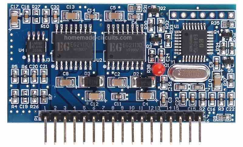
General Datasheet
- Input voltage range: +15V - +20V DC and +5V
- Output voltage range: 110V or 220V AC (depending on the transformer used)
- Output frequency: 50Hz or 60Hz (depending on the configuration of the chip)
- Maximum output power: approximately 300W
- PWM frequency: 16kHz
- Over-current protection: Yes
- Over-voltage protection: Yes
- Under-voltage protection: Yes
- Over-temperature protection: Yes
- Standby power consumption: less than 1W
The EGS002 is designed to work with a center-tapped transformer, and can generate a pure sine wave output waveform using a combination of PWM and SPWM modulation techniques.
It has a low standby power consumption, high efficiency, and comprehensive protection features that make it suitable for small-scale renewable energy applications.
Note that these specifications are general and can vary depending on the specific implementation of the EGS002 inverter board.
It's always best to consult the datasheet or technical specifications provided by the supplier or manufacturer for the specific board you are working with.
Circuit Diagram for External MOSFETs
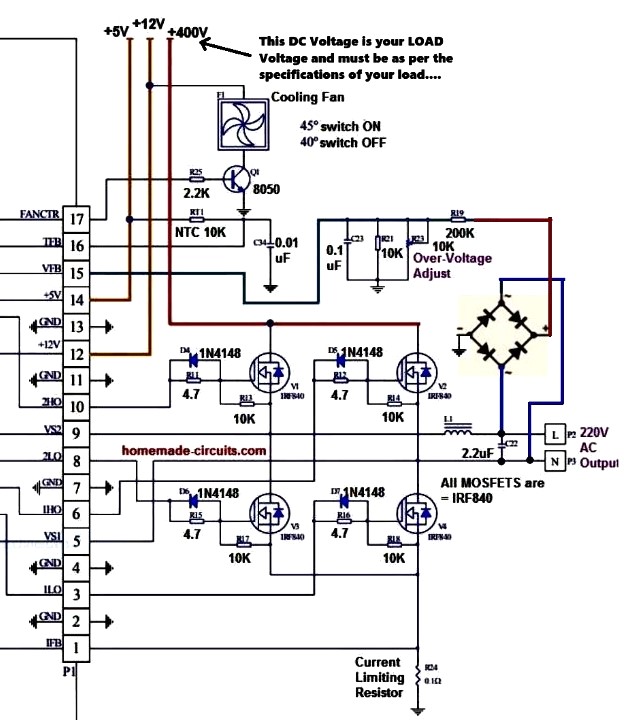
How to Connect
Connecting the EGS002 board to external MOSFETs is feasible, however it needs a few improvements to the board and good knowledge of the circuit design.
Listed below are the recommended methods to connect the EGS002 board to external MOSFETs:
Get rid of the present MOSFETs from the EGS002 board.
This would call for desoldering the MOSFETs from the board and eliminating any associated elements (for example gate resistors and diodes).
Choose the external MOSFETs that you would like to work with.
Ensure these are rated for the voltage and current specifications of your application.
Connect the gate of each external MOSFET to the equivalent gate drive signal on the EGS002 board.
The gate drive signals are generally named as "G" on the board.
Hook up the drain of each external MOSFET to the positive output of the center-tapped transformer.
The positive output of the transformer is normally attached to the positive terminal of the output capacitor.
Hook up the source of each external MOSFET to the negative output of the center-tapped transformer.
The negative output of the transformer is usually attached to the negative pin of the output capacitor.
Insert any essential elements to the circuit, for example gate resistors and diodes, to guarantee correct functioning of the MOSFETs.
Customize the control jumpers on the EGS002 board make it possible for external MOSFET functioning.
This might demand modifying the jumper settings for the "EGS002/04" and "EGS002/05" pins on the board, along with setting up the "EGS002/01" jumper to "ext".
It is critical to remember that changing the EGS002 board in this manner could be complicated and necessitates a great knowledge of the circuit design.
If you are not knowledgeable in electronics or inverter design, it's best to speak with an experienced person or work with a pre-built inverter board that actually contains external MOSFETs
LED Warning Indicator
The EGS002 driver board is equipped with an LED warning alert feature that assists users in identifying potential issues based on the following patterns:
- Normal Operation: The LED remains continuously illuminated.
- Overcurrent Condition: The LED blinks twice, then turns off for a 2-second interval, repeating in a cyclic manner.
- Overvoltage Situation: The LED blinks three times, followed by a 2-second off period, and then repeats this cycle.
- Undervoltage Problem: A sequence of four LED blinks occurs, succeeded by a 2-second pause, and the cycle continues.
- Overtemperature Issue: The LED blinks five times, pauses for 2 seconds, and maintains this cyclic pattern.
Pin Description and Working Details for EGS002
| Pin | Name | I/O | Output Current Feedback/Descriptions |
|---|---|---|---|
| 1 | IFB | I | Pin voltage exceeding +0.5V triggers overcurrent protection |
| 2 | GND | GND | Ground |
| 3 | ILO | O | Right H-bridge Low side MOSFET gate driver output |
| 4 | GND | GND | Ground |
| 5 | VS1 | O | Right H-bridge high-side gate driver return path |
| 6 | 1HO | O | Right H-bridge High side MOSFET gate driver output |
| 7 | GND | GND | Ground |
| 8 | 2LO | O | Left H-bridge Low side MOSFET gate driver output |
| 9 | VS2 | O | Left H-bridge high-side gate driver return path |
| 10 | 2HO | O | Left H-bridge High side MOSFET gate driver output |
| 11 | GND | GND | Ground |
| 12 | +12V | +12V | +12V Input DC voltage input, can be between 10V-15V. |
| 13 | GND | GND | Ground |
| 14 | +5V | +5V | +5V DC supply |
| 15 | VFB | I | AC output voltage feedback to regulate the output voltage, requires +3V to activate. |
| 16 | TFB | I | Temperature monitored with overtemp protection at +4.3V pin voltage |
| 17 | FANCTR | O | Temperature-controlled fan. FANCTR turns the fan on (high output, 1) when above 45°C and off (low output, 0) below 40°C. |
Pinout for LCD Display Connection
| PinOut | Name | I/O | Description |
|---|---|---|---|
| *1 | +5V | Power Input | LCD power supply |
| *2 | GND | Ground | Ground connection |
| *3 | LCDDI | I/O | LCD serial data |
| *4 | LCDCLK | Output | LCD serial clock |
| *5 | LCDEN | Output | LCD chip select |
| *6 | LED+ | Power Input | Backlight power supply |
| *7 | LED- | Ground | Backlight ground connectionpen_spark |
Jumper Setting Details
| Designator | Name | Mark | JP jumper shorted selects [setting description] |
|---|---|---|---|
| 1 | FS0 | JP1 JP5 | JP1 shorted sets AC output to 60Hz Shorting JP5 sets the frequency to 50Hz |
| 2 | SST | JP2 JP6 | JP2 short enables 3s soft start JP6 short disables soft start |
| 3 | DT0 | JP3 JP7 | JP7+JP8 shorted: dead time 300ns JP3+JP8 shorted: dead time 500ns |
| 4 | DT1 | JP4 JP8 | JP4+JP7 shorted: dead time 1.0us JP3+JP4 shorted: dead time 1.5us |
| *5 | LED+ | JP9 | JP9 short: LCD backlight ON JP9 open: LCD backlight OFF |
Default Jumper Settings:
- Output Frequency: 50Hz (JP5 shorted)
- Soft Start: Enabled (JP2 shorted)
- Dead Time: 300ns (JP7 and JP8 shorted)
Jumper Customization:
These jumpers can be manipulated or changed as per users specific needs.
Note:
- Avoid Shorting Conflicting Jumpers: Only one jumper per function can be shorted at a time. For example, you cannot short both JP1 (60Hz) and JP5 (50Hz) simultaneously.
How to Test EGS002 Driver Board
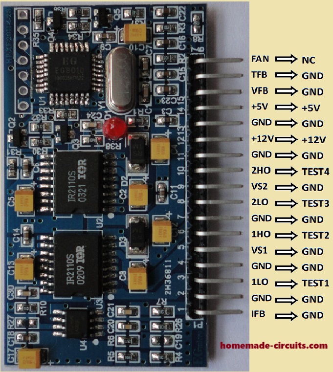
Initial Setup
- Grounding Test Points: During testing, connect the following pins to ground: IFB, VS1, VS2, VFB, and TFB.
- Power Supply Connections:
- Connect +5V DC to the +5V pin.
- Connect +12V DC to the +12V pin (voltage range: 12V to 15V).
Testing Procedure:
Waveform Observation:
- Connect an oscilloscope to test points TEST1 through TEST4 to check the waveforms.
- TEST1 & TEST2: Output fundamental frequency square wave (appears as the blue CH1 waveform in Figure 5-3).
- TEST3 & TEST4: Output unipolar modulation wave. When connected to an RC filter, these points will output the waveform shown as the red CH2 waveform.
Undervoltage Protection Test:
- Since the VFB pin is grounded, the undervoltage protection will activate after 3 seconds.
- This will cause TEST1 through TEST4 to shut down.
- An LED will blink four times, then turn off for 2 seconds, and this cycle will repeat.
- Reconnecting the EGS002 to the power supply will allow you to observe waveforms for another 3 seconds before the undervoltage protection activates again.



Questions & Answers
Thanks alot for all the help you are giving in this platform.
My confussion in the above diagram is that if i use converter to generate 400v. If i use 24v as the primary voltage of the ferrite tranformer. Can i use a 12v battery to get the required 400v of the converter in place of 24v battery.
You can use a 12V battery to generate 400V using a ferrite transformer converter.
Thanks for your help.
I need you to help me with inverter circuit diagram that can operate cold room of any kind.
Please help.
Please provide the intended wattage of the inverter.
It’s 10KVA sir
10KVA is huge, I do not have a 10KVA inverter circuit diagram with me right now. If I find one will let you you.
Ok thanks, what about 5KVA
You will need a full bridge inverter concept and a 5kV transformer having 48V primary side and 220V secondary winding. You will also need a 48 V 1000 Ah battery.
You can investigate the above explained EGS002 inverter circuit using external mosfets to fulfill your requirement.
For the mosfets you can use 10nos of IRF3205 mosfets in parallel on each channel.
I am using irf3205 for the above circuit diagram. Can it handle load voltage up to 400 specified in the diagram?
I have built the converter already. Thanks for your help.
IRF3205 is a 55V mosfet, so it cannot be used with a 400V supply. You must use a 50 amp 500 V or 700 V mosfet
I need your help urgent. I want to sent you a drawing with my idea for your input. i do not know how because there is now way to attach it.
Regards
You can upload it to any free online image hosting site and provide the link to me here, or you can do the same using your Google drive
Sir, when I want to load the inverter with tv, it will be switching on and off but with lights it works. I need your help here
Hi Olusegun, Your TV could be drawing heavy current during initial switch ON which may be causing the voltage to drop and ON/OFF issue. I guess your TV is a CRT TV. Try an LCD TV or an LED TV and check the response.
Thanks for your quick response, it’s LED tv (58″) not the old box tv. The battery voltage drops. I’m using lead acid battery
If the voltage is dropping that indicates a low inverter power specification compared to the load power. You may have to increase the battery and the transformer wattage of the inverter to satisfy the load conditions.
Dear mr Swagatam
I am happy for your education your free education for those in EE need,
My question is,since you listed the power rating of board max 300w.cant i use the board to generate 1000w or more power inverter. If there is internal mosfets,what is the need for more external mosfets.
Thank you for your reply,
Thank you Patrick,
You can definitely use the board to generate 1000 watts by using appropriately rated MOSFETs. This is the advantage of the external mosfets which can be upgraded to higher levels as per the desired specifications.
Sir,
Can I rectify square wave inverter circuit to get 400v for the pure sine wave high frequency inverter?
Olusegun, If it is possible for you to do that, then you can definitely try that.
On the above circuit, under no load, the output voltage is dropping, while the battery voltage is steady. What can I do to solve this problem
That can be difficult to diagnose and troubleshoot without checking your circuit practically.
The voltage is steady now but still low when the VFB is 3v but still low voltage., 148v.
connect your 475nf to 10k verible to achieve 220v
How to charge battery using ESG002, when mains power supply is restored
EGS002 cannot be used to charge battery.
Thanks for your kind words and quick response to all the questions asked by Olusegun.
please what is the transformer voltage for pure sine wave 12v inverter. 7v or 12v??
Thank you Samuel,
It should be 7 V, if the inverter is a Sine-PWM inverter
Sir now when I want to increase the mosfets to 8 the voltage reduces to 160v. What can I do to solve this problem
You can check the current by connecting an ammeter in series with the battery positive line. Without an output load it should not be more than 50 mA depending upon the transformer power specifications. If it shows a high consumption, will indicate a fault somewhere.
Thanks for your quick response, I so much appreciate this about you.
I detected that I used different mosfets that are not of the same rating. They have different current and voltage rating. I might still get back to you soon.
OK, thanks for updating!
Now when I connected irfz44 , 8 pieces now the voltage is normal now. Thanks a lot.
Good to know the problem is solved.
Hie, thanks for this lecture. I made the inverter using the egs002 it’s working perfectly. I have a question, Have you ever tried to generate these pwm and spwm using Arduino uno or nano? If yes lead me to the post, if no please try it out for me.
Hi, thanks!
For Arduino based SPWM circuits you can refer to the following posts:
https://www.homemade-circuits.com/arduino-pure-sine-wave-inverter-circuit/
https://www.homemade-circuits.com/arduino-spwm-generator-circuit/
Hello sir, it’s me again, I’ve done with the 12v successfully, I want to use 24v battery. What mosfet can I use and the voltage of the transformer too. Thanks.
Olusegun, do you want to use 24V in place of 400 V in the EGS circuit??
Yes, I want to use 24v
MOSFETs can be IRF540, and the transformer primary can be 0-12V
Hello sir, thanks for these circuits you researched and made available for the use of all. I built this egs002 inverter circuit and it worked. I used a 12v 4s lifepo4 battery hence my power supply is usually 13v or above. Now the problem I encounter is that the circuit will run 2 seconds and off, the led on the egs002 will blink 4 time and ON the output again, this will keep recycling. The datasheet I found on the internet said this means under voltage condition. But 12.6v that gets to the chip is not supposed to be under voltage.( I get 12.6 because I put a diode at the input to protect the chip from mistaken polarity swap, but the problem is the same even when I removed the diode and power it directly) The diagram above showed +5, +12, +400. But On the general datasheet , you wrote +15 – +20. Can this be responsible for my difficulty? Any suggestions you provide to help me rectify this will be highly appreciated
Thank you Ugo for the detailed explanation.
I referred to the datasheet online and found the following information:
EGS002 driver board provides LED warning indication function. User can determine problem
according to the followings:
Normal:Lighting always on
Overcurrent:Blink twice, off for 2 seconds, and keep cycling
Overvoltage:Blink 3 times, off for 2 seconds, and keep cycling
Undervoltage:Blink 4 times, off for 2 seconds, and keep cycling
Overtemperature:Blink 5 times, off for 2 seconds, and keep cycling
Thanks for your response sir. The difficulty in my case is , my voltage is not low(13-13.2 ) almost always. But I get the 4 blink signal
Yes I understand, in that case it is difficult to diagnose the issue.
I used a 9v primarily transformer and irf460 mosfet , its a 20amps high voltage mosfet I tend to swap the input of the mosfet to 400v after succesful test. In the mean time I read a little above 9v output from mosfet to transformer, and 204v at the transformer output , I have not connected the output reference yet to correct the output,this is because I configured it as it is in the diagram above , the transformer is temporary. Ihope i provided enough information for clear understanding of the situation
Hello sir, I have successfully built a 3kva of this inverter. It’s working perfectly with no complain. My problem is how to use one low frequency transformer for both inverter and charger system. Is it possible, if yes, how?
Thank you Olusegun, I am glad you could build the design successfully. However, i am sorry, I have no idea how to convert the above design into a single transformer inverter/charger circuit.
Ok thanks
Please sir, for 24v inverter can I use LM7805 instead of LM7812, or can I use both
Hi Soliu,
As given in the diagram, in place of 5V you will have to use 7805 and in place of 12V you will have to use 7812
Could this be used a sine function generator, instead of power?
I guess the sine output is PWM not sinusoidal.
As I can see in the circuts diagram, each mosfet is connected to a specific pin of the egs002 module.
My question is, if I need more than 4 mosfet where are they going to be connected?
Why do you want more than 4 number? Do you want to increase the power of the MOSFETs? In that case you can simply add the MOSFETS parallel to the existing ones.
If I need a 2000 watts inverter from this circuit, what type of mosfet is good for handling the power and what is the rating of transformer do I need to use?
Thanks very much
You can try adding the following MOSFET:
https://www.homemade-circuits.com/high-current-mosfet-irfp2907-for-wind/
Please how do I shorten JP for it’s operation example i was told to shorten JP5 to get 50HZ frequency. please what does it mean on the EGS002 Board am using this board for the first time. help
I too can’t figure out what is JP5 in the EGS002? Never heard of this term.
Hi,I recently searched for EGS032 three phase inverter module and that leads to this page, Mr swagatam can you explain about EGS032 module pinout?
Hi Luis,
I have not yet studied the EGS032 three phase inverter module, so cannot explain its pinouts at this moment, I will try to get more information about this module so that I can create a new article on this topic.
Ok, thanks sir
Hi, i used EGS002 along with conventional UPS 6.5v Transformer to have pure sine inverter, but with loads heavier than 150w, the voltage drops from 200v to 180v. Any idea where to look at ? thanks. Feedback seems correct (always 3v at VFB pin)
If the output voltage is dropping then you may have to consider upgrading the battery, transformer and the MOSFETs, or whichever is below the required current and wattage specifications.
Thanks for your answer.
I run 12v under powerfull power supply, the transformer comes from a 500w UPS and i am using 3205 mosfets. Isn’t the problem coming from the feedback circuit ?
In that case you can temporarily disconnect the feedback and check the response, that will confirm if the feedback is responsible or not.
Thanks for this tip. Should i ground it or leave it floating.
Also, when lowering the voltage to 170v, it can power 100W without any voltage drop, the only thing is that VFB = 1v.
Did you try adjusting the 10k preset?
If you are not using the feedback, you can keep the pinout gounded.
Hello, i use the 10K preset to reach 220V without load, once loaded the same problem. Note that rectified DC voltage is 217VDC, and voltage at VFB is always 1V, not 3V as mentionned in the datasheet, and the EGS strangely doesn’t go into low voltage fault.
If your input DC is 217v at the MOSFET drains then the output should be much lower than 217v, in fact it should be 217/1.41=153v rms, isn’t it?
I was speaking about DC voltage at the rectification diodes in the feedback circuit. As said before, VFB pin sees only 1V when AC voltage is 220V and under load, AC voltage drops to 170V and VFB at 0.7V.
How come it doesn’t go into under voltage fault?
OK, what happens if the VFB connection is removed? What is the Amp rating of the power supply?
I am not fully aware of the under voltage cut off setting, is there any setting for this?
Hi,Mr swagatam,now I’m build a basic inverter using the egs002, like the circuit diagram above, and works perfectly ?, and when I use a 5kw transformer with same 60w fan as load,the mosfets irfp2907 blew up, not instantly, but after several minutes working, the question is can be the impedance of the transformer affect the mosfet?, there is no high temperature on mosfet, no bad frequency noise,every thing runs fine, until failure
Hi Luis, glad you could build the inverter design successfully.
Yes the transformer impedance can cause MOSFETs to get overloaded and blow, however that would also cause the MOSFETS to heat up first. In your case the MOSFETS are not heating up and we also have the overload current protection included in the design, so I don’t think it is the transformer impedance which is causing the issue. Possibly it could be he high frequency spikes responsible for this.
You can try adding reverse diodes across the drain, source of the MOSFETS, and see if that helps to solve the problem.
Ok thanks sir for the help!
If the egs002 module indicate overcurrent with no load,what should I do.some egs002 work ok but some blink indicating overcurrent.sir,what should I do.thank you
If it is indicating over current without a load that means either your MOSFETs are shorted or has some fault or maybe the EGS002 itself is malfunctioning. Disconnect the drains of the MOSFETs and check again.
Mr swagatam, I’m following the project with egs002 module, and I’m interested about the totem pole driver for mosfets, do you have an available circuit? ,for 5A output
Hello Luis, i am not sure if a totem pole BJT driver can be used for the high side MOSFETs? I think it can’t be used for the high side MOSFETs.
Right,I’m thinking for increasing mosfets gate signal it may work
How will you increase gate voltage to EGS002 MOSFETs?
Hi guys!
How can I reset the EGS002?
Hi, what exactly do you want to reset? Egs002 is an oscillator based circuit, it does not have a memory or storage facility to be reset.
Hi, thanks for your reply.
I found the information below on the EG8010 datasheet and I want to know how I can do the hard reset as it is stated below as the EGS002 module I’m using is not coming on again.
Thanks.
“If overvoltage or undervoltage issue still exists, EG8010 will repeat the
process above every eight seconds. If EG8010 runs regularly for more than one minute, it will zero
the counter of overvoltage and undervoltage. However, if EG8010 does not function regularly after
five 8-second cycle, it will complete turn off the output of SPWM unit. It needs a hard reset to start
again.’
OK, got it…however currently I do not have any information regarding how to hard reset an egs002 module…let us know if you are able to find it.
Thank you.
What do I do if the LED keeps blinking thrice and going off again and again. Pin 15 (Vfb) is not connected to anything and yet I get overvoltage signalling. How can I remedy this?
Please connect pin#15 to ground and check again, if still the LED blinking does not stop then your board might be malfunctioning.
I try to build 1kva low frequancy hbrige used sg3525 IC my problem is feedback
please see the link beloww…it shows how to configure the feedback to pin#1 of the IC from the output 220V of the inverter:
Hello sir, I use the external mosfet circuit diagram for the EGS002 module to create a genuine wave with a standard frequency of 60 hz/ 100v /300W.
I applied voltage (x vol DC) to the mosfet bridge so that the output voltage was 100v AC.
I would like to ask you, can I get that external voltage of x vol DC from another transformer source? Of course, that DC source has enough current for a capacity of 300 W.
Hello Thieu, yes that’s definitely possible, you can use an external DC supply for the H-Bridge configuration, and the load.
This EGS002 module would have been a great module if it has the ability to function as an uninterrupted power supply “UPS” ie be able to switch from battery mode to an AC main mode and charge back the battery when the AC mains returns.
Hi sir, i did the design,but got the problem that led blinks 4 time then shut dowm then after 2secs,the board start and repeats the cycle. Am also getting 300v at the output,the preset seems not adjusting the output. How do I solve the issue sir,will really appreciate your quick response.
Hi Evans, from your LED indication, it seems like a battery undervoltage problem.
This could be happening due to a discharged battery or an overload.
Please check the setup without connoting any load at the output.
Dear Sir.
I don’t know if the EGS002 I bought has a defect due to the manufacturer, but I had to adjust the 200k resistor on the VFB battery up to 400k for it to work normally.
I power the Mosfet with 110v Ac (of course it must be converted to DC) and the output is 100v AC. So a loss of 10%.
I used an Oscilloscope (old model Analog) to observe the sine wave and found that the sine wave was correct, but I wondered if there was a problem with the inverter current. I used a digital meter to measure the voltage, and the following happened:
– Measured with an analog meter Or a Chinese digital clock (cheap) will read the numbers normally
– Measured with a standard European digital clock (bought in Poland), the number will flash continuously as if the electrical pulse is intermittent.
I’m testing running 100v/ 60 hz devices on that EGS inverter.
Hello Thieu,
The resistive divider at pin#15 using 200k and 10k preset determines the output voltage level. So if you have adjusted the 200k to 400k for the intended output AC level, then it is fine according to me.
If the output is sinewave then there will be a loss of voltage due to RMS conversion. Please check the peak voltage, it should be 110V.
Please check the output voltage by adding some load at the output. Voltmeter cannot verify current specification, to verify current you can connect an ammeter in series with the load.
Hello sir, Yes, the maximum voltage when micro-adjusting R10k is up to 110vAC.
If set to 110 vAC, the voltage will decrease depending on the load, so I set the output from 100v to 103v so there will be no voltage drop under load.
I checked the temperature and it’s normal.
What I’m still wondering is that when there is a load, it consumes too much current at the input. ( I haven’t measured the input current but I hear a humming sound at the input power transformer).
Hello Thieu,
If the input voltage to the H-bridge MOSFET is 110V DC, then the AC sine wave output cannot be 110V, it should be around 110 / 1.41 = 78V AC RMS.
Hello sir, maybe it’s because Google’s translation from Vietnamese is not accurate.
My EGS still complies with DC mosfet input/AC output of 140v/ 1.41=99.3 v(AC).
It’s not about the MOSFETs, I was referring to the AC output to the load, it will be lower than the input DC. If input DC is 110V, the output will be 78V AC RMS.
Hello sir, I still do not understand the capacity of the H-bridge inverter, so I would like to ask you that the H-bridge has 2 pairs (ie 4 mosfet) each mosfet has a capacity (for example: 125w), then the capacity of the inverter will be 125 W or 250W.