• Skip to main content
  • Skip to primary sidebar

Homemade Circuit Projects

Need circuit help? Post them in the comments! I've answered over 50,000!

Blog | Categories | About | Contact | Calculators-online
You are here: Home / Sensors and Detectors / Digital Up/Down Volume Control Circuit

Digital Up/Down Volume Control Circuit

Last Updated on January 1, 2019 by Swagatam 2 Comments

In this post I have explained a simple digital volume control circuit using the IC DS1668 which can be used in amplifiers and all audio equipment for achieving a push button press up/down volume control facility.

What are Electronic Rheostats

The DS1668 and DS1669 Dallastats are electronic rheostats or potentiometers. These devices present 64 possible consistent tap points over the resistive array as they are supplied with regular variations of 10K, 50K, and 100K ohms.

The Dallastats can be governed by either a mechanical-type contact closure input or a electronic digital means input for instance a CPU.

Wiper placement is taken care of without the benefit of power that could be achieved by means of the use of a EEPROM storage cell assembly. The EEPROM cell array is definitive to understand higher than 80,000 writes.

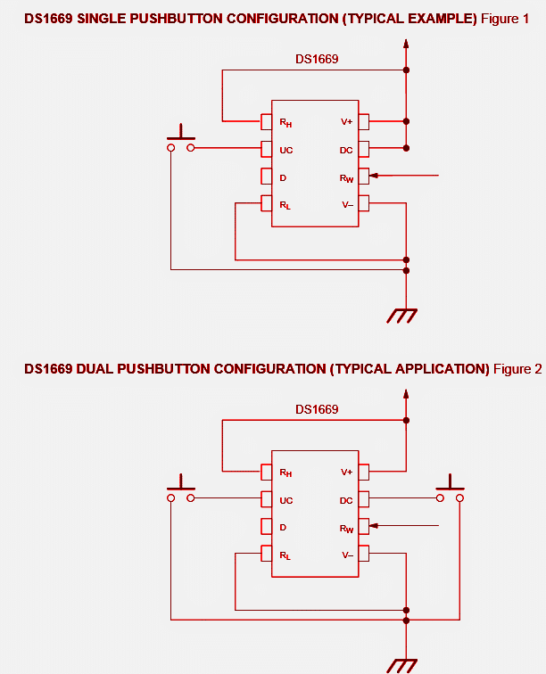
The DS1668 and DS1669 are different in the style packages in which they are available. The DS1668 is merely obtainable in a personalized 6-pin package with an individual integrated push button as shown in the package drawing.

Role of Push Buttons

The individual integrated push button offers the mechanised control input of the wiper point.

Furthermore, a digital supply input, D, enables the potentiometer to be operated by a microcontroller or processor.

Supplementary package pins incorporate the positive voltage input +V, the negative voltage input, -V, the resistor wiper , RW, along with the high resistor . RH.

The DS1668 is graded for professional temperature application exclusively (OTC to 70YC). The DS1669 may come conventional IC packages such as an 8-pin 300 mil DIP and an 8-pin 200 mil SOIC. Such as the DS1668, the DS1669 could be set up to utilize using an individual push button or electronic source input.

This is drawn out in Figure 1. Furthermore, the DS1669 could be designed to control in a twin push button arrangement that could be seen in Figure 2.

The DS1669 pinouts make it possible for use of each ends of the potentiometer RL, RH, along with the wiper, RW. Control inputs consist of the digital source input, D, the up contact input, UC, as well as the down contact input, DC.

Additional package pinouts involve the positive,+V, and negative, -V, sup- ply inputs. The DS1669 can be found in professional or industrial temperature variations.

OPERATIONAL SPECIFICATIONS

The DS1668/DS1669 Dallastats are regulated by means of a contact closure input or by a digital base input.

The DS1668 is designed to function from just one contact closure (pushbutton) input that may be built in the personalized 6-pin package or the product could be powered from the digital supply input (D).

The DS1669 could be con- trolled making use of one push switch input, combined push switch, or employing the digital supply input.

You'll also like:

  • fig1Deep Soil Metal Detector Circuit – Ground Scanner
  • RF detector circuit using transistors2 Simple RF Detector Circuits Explored
  • home electromagnetic radiation detector circuitHome Electromagnetic Radiation Detector Circuit
  • metaldetectorcircuit9 Simple Metal Detector Circuits Explained

Filed Under: Sensors and Detectors Tagged With: Control, Digital, Down, Volume

About Swagatam

I am an electronics engineer and doing practical hands-on work from more than 15 years now. Building real circuits, testing them and also making PCB layouts by myself. I really love doing all these things like inventing something new, designing electronics and also helping other people like hobby guys who want to make their own cool circuits at home.

And that is the main reason why I started this website homemade-circuits.com, to share different types of circuit ideas..

If you are having any kind of doubt or question related to circuits then just write down your question in the comment box below, I am like always checking, so I guarantee I will reply you for sure!

Previous Post: « Power Switch ON Alarm with Auto OFF Circuit
Next Post: How to Measure Dissolved Oxygen in Liquids »

Reader Interactions

Comments

style says:
October 23, 2014 at 5:59 am

Hello sir
this IC is available in mumbai. or can we purchase online
regards

Reply
Swagatam says:
October 23, 2014 at 2:04 pm

Hello style, TDA8551 most probably will be available in mumbai, or you can also purchase it online…

Reply

Leave a Reply to style Cancel reply

Your email address will not be published. Required fields are marked *

Primary Sidebar

circuit simulator image


Subscribe to get New Circuits in your Email


Categories

  • Arduino Projects (92)
  • Audio and Amplifier Projects (132)
  • Automation Projects (17)
  • Automobile Electronics (101)
  • Battery Charger Circuits (84)
  • Datasheets and Components (109)
  • Electronics Theory (148)
  • Free Energy (39)
  • Games and Sports Projects (11)
  • Grid and 3-Phase (19)
  • Health related Projects (25)
  • Home Electrical Circuits (12)
  • Indicator Circuits (16)
  • Inverter Circuits (94)
  • Lamps and Lights (157)
  • Meters and Testers (71)
  • Mini Projects (28)
  • Motor Controller (66)
  • Oscillator Circuits (28)
  • Pets and Pests (15)
  • Power Supply Circuits (90)
  • Remote Control Circuits (50)
  • Security and Alarm (64)
  • Sensors and Detectors (105)
  • SMPS and Converters (32)
  • Solar Controller Circuits (60)
  • Temperature Controllers (43)
  • Timer and Delay Relay (49)
  • Voltage Control and Protection (38)
  • Water Controller (36)
  • Wireless Circuits (30)


Other Links

  • Privacy Policy
  • Cookie Policy
  • Disclaimer
  • Copyright
  • Videos
  • Sitemap


People also Search

555 Circuits | 741 Circuits | LM324 Circuits | LM338 Circuits | 4017 Circuits | Ultrasonic Projects | SMPS Projects | Christmas Projects | MOSFETs | Radio Circuits | Laser Circuits | PIR Projects |

Social Profiles

  • Twitter
  • YouTube
  • Instagram
  • Pinterest
  • My Facebook-Page
  • Stack Exchange
  • Linkedin


Recent Comments

  • Swagatam on 3 Laser Beam Controlled Circuits Explored
  • ken on 8X Overunity from Joule Thief – Proven Design
  • Kim on 3 Laser Beam Controlled Circuits Explored
  • Swagatam on Making an Adjustable Electromagnet Circuit
  • Swagatam on Make this DC CDI Circuit for Motorcycles

© 2025 · Swagatam Innovations