A circuit which enables a user to linearly control the speed of a connected motor by rotating an attached potentiometer is called a motor speed controller circuit.
5 easy to build speed controller circuits for DC motors are presented here, first one using MOSFET IRF540, second one using IC 555, the third concept with IC 4093, fourth design involves the IC 741, while the fifth design utilizes IC 556, featuring torque processing
Design#1: Mosfet based DC Motor Speed Controller
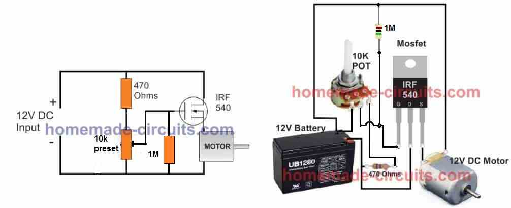
A very cool and easy DC motor speed controller circuit could be build using a just a single mosfet, a resistor, and a pot, as shown below:
Using a BJT Emitter Follower
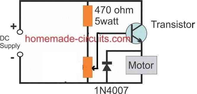
As can be seen the mosfet is rigged as a source follower or a common drain mode, to learn more about this configuration you may refer to this post, which discusses a BJT version, nevertheless the working principle remains the same.
In the above DC motor controller design, the pot adjustment creates a varying potential difference across the gate of the mosfet, and the source pin of the mosfet simply follows the value of this potential difference and adjusts the voltage across the motor accordingly.
It implies that the source will be always 4 or 5V lagging behind the gate voltage and vary up/down with this difference, presenting a varying voltage between 2V and 7V across the motor.
When the gate voltage is around 7V, the source pin will supply the minimum 2V to the motor causing a very slow spin on the motor, and 7V will be available across the source pin when the pot adjustment generates the full 12V across the gate of the mosfet.
Here we can clearly see that the mosfet source pin seems to be "following" the gate and hence the name source follower.
This happens because the difference between the gate and the source pin of the mosfet must be always around 5V, in order to enable the mosfet to conduct optimally.
Anyway, the above configuration helps to enforce a smooth speed control on the motor, and the design could be built quite cheaply.
A BJT could be also used in place of the mosfet, and in fact a BJT would produce a higher control range of about 1V to 12V across the motor.
Video Demo
When it comes to controlling motor speed uniformly and efficiently, a PWM based controller becomes the ideal option, here I have explained more, regarding a simple circuit to implement this operation.
Also Read: High Voltage DC Motor Controller Circuit
Using MOSFET as a High Power Potentiometer
The next figure below shows a very simple DC motor speed controller circuit that employs a MOSFET as a high-power potentiometer (rheostat). The circuit is designed to work with 12 volt DC motors having a peak current usage of below 5 amp.
The mains AC supply is provided through the on/off switch S1 to the primary winding of the isolation and step-down transformer T1.
The push-pull rectifier circuit of D1 and D2 full-wave rectifies T1's output, and the resulting unfiltered DC output is smoothed to a certain extent by C1 to produce a relatively constant DC potential.
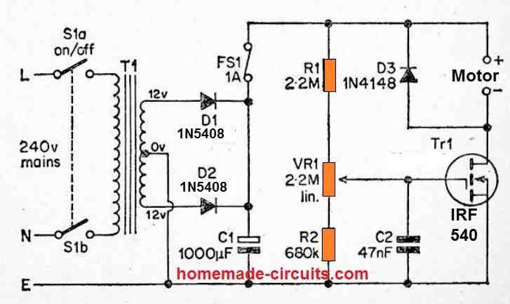
There can be a significant level of ripple on this DC output, however it is unimportant in this application. Tr1 provides power to the load and is biased through a resistive divider circuit consisting of R1, VR1, and R2.
The gate bias voltage provided to Tr1 might not be adequate to allow the MOSFET to conduct meaningfully with the wiper of VR1 at the R2 end of its rotation, and the motor will not operate.
Advancing the wiper of VR1 towards the opposite end of its rotation allows a constantly increasing bias to be supplied to Tr1, resulting in a steadily decreasing drain to source resistance.
Because of this, the power delivered to the motor rises in tandem with the motor's speed, until Tr1 reaches saturation (where the motor runs at its full speed).
VR1 may therefore be used to change the motor's speed from minimum to maximum speed.
C2 filters away any amount of mains hum or other electrical noise that could otherwise be picked up by Tr1's high impedance gate circuit, preventing the motor speed from being reduced to zero.
D3 is a safety diode that inhibits any excessive reverse voltage spikes that may occur as a result of the motor's excessively inductive load.
Design#2: PWM DC Motor Control with IC 555
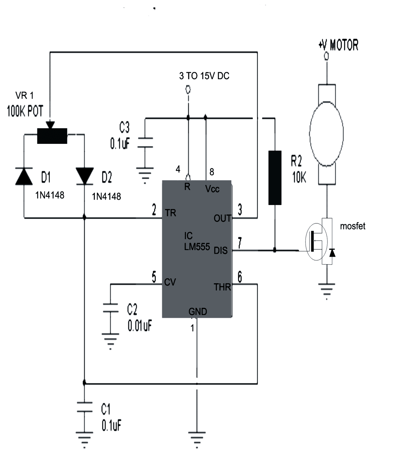
The design of a simple motor speed controller using PWM may be understood as follows:
Initially when the circuit is powered, the trigger pin is in a logic low position since the capacitor C1 is not charged.
The above conditions initiates the oscillation cycle, making the output change to a logic high.
A high output now forces the capacitor to charge via D2.
On reaching a voltage level that's 2/3 of the supply, pin #6 which is the threshold of the IC triggers.
The moment pin #6 triggers, pin #3 and pin #7 reverts to logic low.
With pin #3 at low, C1 yet again begins discharging via D1, and when the voltage across C1 falls below the level that's 1/3 of the supply voltage, pin #3 and pin #7 again become high, causing the cycle to follow and go on repeating.
It is interesting to note that, C1 has two discretely set paths for the process of charging and discharging via the diodes D1, D2 and through the resistance arms set by the pot respectively.
It means the sum of the resistances encountered by C1 while charging and discharging remains the same no matter how the pot is set, therefore the wavelength of the out put pulse always remains the same.
However, since the charging or the discharging time periods depends upon the resistance value encountered in their paths, the pot discretely sets the these time periods as per the its adjustments.
Since the charge and discharge time periods is directly connected with the output duty cycle, it varies according to the adjustment of the pot, giving form to the intended varying PWM pulses at the output.
The average result of the mark/space ratio gives rise to the PWM output which in turn controls the DC speed of the motor.
The PWM pulses are fed to the gate of a mosfet which reacts and controls the connected motor current in response to the setting of the pot.
The current level through the motor decides it speed and thus implements the controlling effect via the pot.
The frequency of the output from the IC may be calculated with the formula:
F = 1.44(VR1*C1)
The mosfet can be selected as per the requirement or the load current.
The circuit diagram of the proposed DC motor speed controller can be seen below:
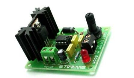
Prototype Image:
Video Testing Proof:
In the above video clip we can see how the IC 555 based design is used for controlling speed of a DC motor. As you may witness, although the bulb works perfectly in response to the PWMs and varies its intensity from minimum glow to maximum low, the motor does not.
The motor initially does not respond to the narrow PWMs, rather starts with a jerk after the PWMs are adjusted to significantly higher pulse widths.
This does not mean the circuit has problems, it is because the DC motor armature is held between a pair of magnets tightly.
To initiate a start the armature has to jump its rotation across the two poles of the magnet which cannot happen with a slow and gentle movement. It has to initiate with a thrust.
That's exactly why the motor initially requires a higher adjustments for the PWM and once the rotation is initiated the armature gains some kinetic energy and now achieving slower speed becomes feasible through narrower PWMs.
However still, getting the rotation to a barely moving slow status can be impossible because of the same reason as explained above.
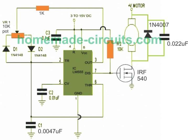
I tried my best to improve the response and achieve a slowest possible PWM control by making a few modifications in the first diagram as shown below:
Having said this, the motor could show a better control at the slower levels if the motor is attached or strapped with a load through gears or pulley system.
This may happen because the load will act as a damper and help to provide a controlled movement during the slower speed adjustments.
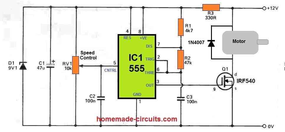
Another Simple PWM DC Motor Controller Circuit
Design#3: DC Motor Controller with Multiple Features
The following DC motor controller circuit provides multiple control features such as:
- PWM Speed Control.
- Direct Speed Without PWM Speed Control (with slow Initialization).
- Forward/Reverse.
- Sudden Brake.
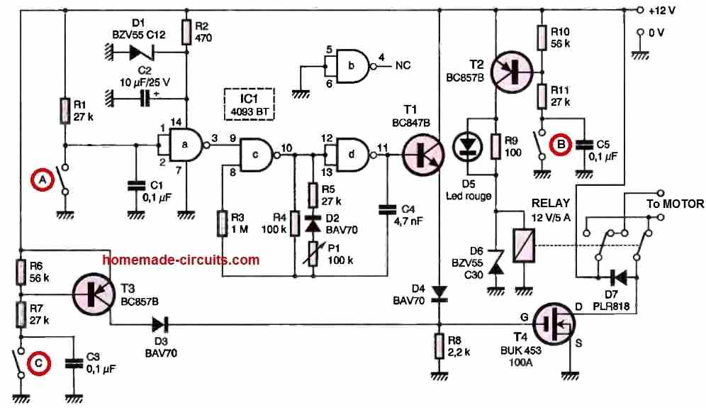
When Switch A is pressed, the PWM function kicks in and the motor speed can be regulated by moving the potentiometer P1.
Pressing Switch B ON or OFF causes the motor to change direction between anticlockwise and clockwise motions. Meaning this switch B can be used to enable reverse/forward motion on the motor.
Regardless of the Switch A position, if Switch C is pressed, causes the motor to attain a direct full speed. In this position the PWM function does not work.
If Switch A and Switch C are both open, then the motor will remain switched OFF.
Design#4: Using a Single Op amp
The op amp circuit described below can be used for regulating the speed and direction of a motor. It functions as a voltage follower, with its positive input (pin #3) linked to potentiometer R3, which functions as a dual-purpose controller for motor speed and direction.
At the mid-point of the potentiometer's range, the op amp output is close to zero, causing neither Q1 nor Q2 to conduct current.
Moving the potentiometer wiper towards the positive side will make the op amp output become positive, allowing Q1 to conduct current to the motor and increase its speed.
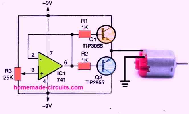
Adjusting the potentiometer towards the negative supply will cause the op amp output to swing to a negative voltage, resulting in Q2 turning on while Q1 is turned off. This action reverses the motor's rotation direction.
Depending on the rotation direction, the motor's speed increases as the potentiometer wiper is pulled towards either end of its range.
To determine the maximum acceptable DC voltage range for the selected motor, it may be necessary to monitor the voltage variation on the emitters of Q1 and Q2.
Design#5: Using IC 556 for Enhanced Speed Control
Varying a DC motor velocity may appear to be not so difficult and you may find plenty of circuits for it.
However these circuits do not guarantee consistent torque levels at lower motor speeds, making the functioning quite inefficient.
Moreover at very low speeds due to insufficient torque, the motor tends to stall.
Another serious drawback is that, there’s no motor reversal feature included with these circuits.
The proposed circuit is completely free from the above shortcomings and is able to generate and sustain high torque levels even at lowest possible speeds.
Circuit Operation
Before I have explained the proposed PWM motor controller circuit, we would also want to learn the simpler alternative which is not so efficient.
Nonetheless, it may be considered reasonably good as long as the load over the motor is not high, and as long as the speed is not reduced to minimum levels.
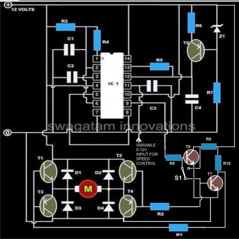
The figure shows how a single 556 IC can be employed for controlling speed of a connected motor, we won’t go into the details, the only notable drawback of this configuration is that the torque is directly proportional to the speed of the motor.
Coming back to the proposed high torque speed controller circuit design, here we have used two 555 ICs instead of one or rather a single IC 556 that contains two 555 ICs in one package.
Circuit Diagram
Main Features
Briefly the proposed DC motor controller includes the following interesting features:
Speed can be varied continuously right from zero to maximum, without stalling.
The torque is never affected by the speed levels and remains constant even at minimum speed levels.
The motor rotation can be flipped or reversed within a fraction of second.
The speed is variable in both the directions of the motor rotation.
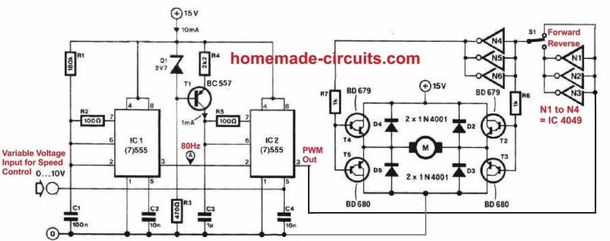
The two 555 ICs are assigned with two separate functions. One sections is configures as an astable multivibrator generating 100 Hz square wave clocks which is fed to the preceding 555 section inside the package.
The above frequency is responsible for determining the frequency of the PWM.
The transistor BC 557 is used as a constant current source which keeps the adjoining capacitor at its collector arm charged.
This develops a saw-tooth voltage across the above capacitor, which is compared inside the 556 IC with the sample voltage applied externally over over the shown pin-out.
The sample voltage applies externally can be derived from a simple 0-12V variable voltage power supply circuit.
This varying voltage applied to the 556 IC is used to vary the PWM of the pulses at the output and which eventually is used for the speed regulation of the connected motor.
The switch S1 is used to instantly reverse the motor direction whenever required.
Parts List
- R1, R2, R6 = 1K,
- R3 = 150K,
- R4, R5 = 150 Ohms,
- R7, R8, R9, R10 = 470 Ohms,
- C1 = 0.1uF,
- C2, C3 = 0.01uF,
- C4 = 1uF/25VT1,
- T2 = TIP122,
- T3, T4 = TIP127
- T5 = BC557,
- T6, T7 = BC547,
- D1---D4 = 1N5408,
- Z1 = 4V7 400mW
- IC1 = 556,
- S1 = SPDT toggle switch
The above circuit was inspired from the following motor driver circuit which was published long back in elecktor electronic India magazine.
Controlling Motor Torque using IC 555
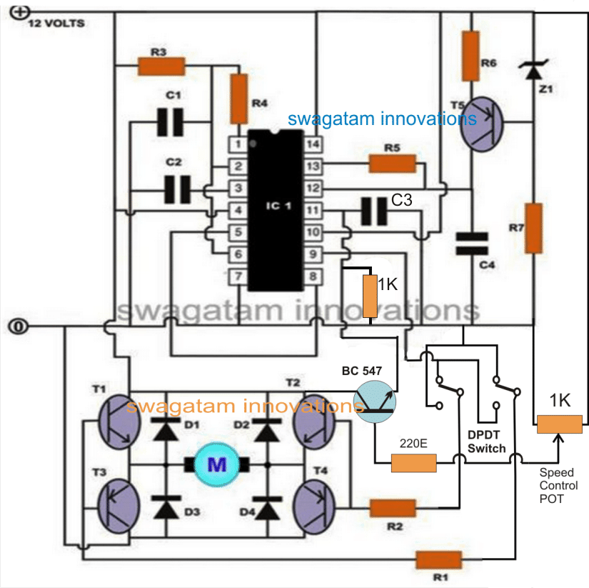
The first motor control diagram can be much simplified by using a DPDT switch for the motor reversal operation, and by using an emitter follower transistor for the speed control implementation, as shown below:
Improved Torque at Low Speed using CMOS PWM Control
Although the single MOSFET linear motor speed controller layouts explained at the beginning of the article includes the benefit of simplicity, but these may have a handful of down sides.
One of them is that there exists a significant level of dissipation in the MOSFET, specifically when the motor is tweaked for approximately 50 percent of the optimum speed.
This may be certainly not a serious issue however, and just requires the installing of a moderately large heatsink on the MOSFET.
A much more critical concern is that the motor is likely to stall as soon as this kind of linear controller is adjusted for any lower speeds.
This is because the MOSFET in this situation has a relatively high resistance, which offers the supply input with a significantly high output impedance.
When the load on the motor is increased, it attempts to draw excessive amounts of supply current, but this leads to a larger voltage drop across the transistor and a lower supply voltage across the motor.
As a result, the power delivered to the motor does not vary significantly, rather it decreases. Due to this, the motor has a propensity to stall.
Also, there is an opposite reaction in which lowering the load on the motor cuts its current drain, resulting in a greater supply voltage and a significant rise in motor speed.
Using a controller that provides a pulsed PWM signal to the motor, you may achieve much better motor speed management.
Improved Torque using CMOS PWM Speed Control
One method of implementing this, and the one employed here, is to have a circuit that provides a fixed output pulse duration while altering the frequency of the pulses to modify the motor speed. A low frequency produces long gaps between pulses and feeds a relatively low power to the motor.
When the frequency is increased, there are no noticeable gaps between the pulses, and the motor receives a nearly constant signal.
This results in a high average power in the motor, which runs at full speed.
The benefit of this system is that when the motor is being pulsed, it is essentially getting the full power during the ON periods of the pulses, and is free to consume a large supply current if the load on the motor actually demands it.
As a result, the motor is powered by a sequence of strong pulses that defy stalling and provide improved torque even at reduced speeds.
The following figure depicts the circuit diagram of a pulsed DC motor speed control. Here, T1, D1, D2, and C1 derive a sufficient DC supply from the mains AC supply.
Tr1 is hooked up in series with the motor, but its gate terminal receives the output signal from an astable multivibrator circuit.
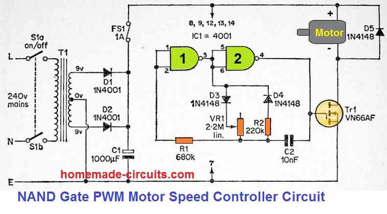
This pwm circuit is built using two of the four gates of a CMOS 4001 device, which are utilized in a CMOS astable setup that is quite a conventional design.
A couple of timing resistors can be seen connected between the output of gate 1 and the junction of R1 and C2, which differs from the conventional PWM design.
VR1 and R2 are the two resistors, along with guiding diodes D3 and D4 connected in series with the output of NAND gate 1.
The two diodes ensure that R2 works like the timing resistance whenever the astable's output is high, and VR1 functions as the timing resistance whenever the output is low.
The period of the output pulses is constant since R2 has a predetermined value. The interval between them could be changed by varying VR1.
This will be nearly zero when it is adjusted for lowest resistance. The output mark space ratio is greater than ten to one at maximum resistance.
VR1, therefore, could be adjusted to generate the desired motor speed with effective torque, with the lowest speed happening at full resistance and the highest speed occurring at zero resistance.
Precision Motor Control using a Single Op Amp
An extremely refined or intricate control of a d.c. motor could be achieved making use of an op-amp and a tacho-generator.
The op-amp is rigged as a voltage sensitive switch. In the circuit demonstrated below, as soon as the output of the tacho-generator is lower than the preset reference voltage the switching transistor be turned ON and 100 % power will be provided to the motor.
Switching action of the op amp would happen in just a couple of millivolts around the reference voltage. You will need a dual power supply, which may be just zener stabilized.
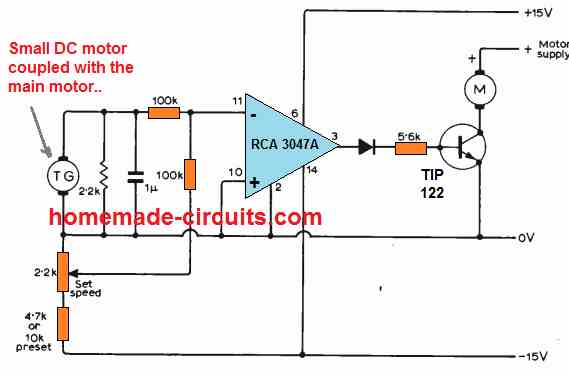
This motor controller enables infinitely adjustable range without involving any form of mechanical hassles.
The op amp output is only +/- 10% of the supply rails level, thus employing a double emitter follower huge motor speeds could be controlled.
The reference voltage could be fixed through thermistors, or an LDR etc.
The experimental set up indicated in the circuit diagram made use of an RCA 3047A op amp, and a 0.25W 6V motor as tacho-generator which generated around 4V at 13000 r.p.m for the intended feedback.
Additional DC Motor Controller Designs:
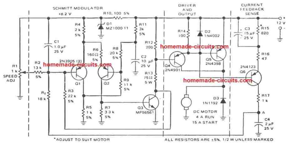
PWM Motor Control using Only BJTs
The following circuit also uses PWM principle for the desired motor speed control, however, it does not depend on any integrated circuits or ICs, rather uses only ordinary BJTs for the implementation. I got this from an old magazine page.
Motor Control Circuits using LM3524
The IC LM3524 is a specialized PWM controller circuit which allows us to configure very useful and precision motor speed control circuits as I have explained below:
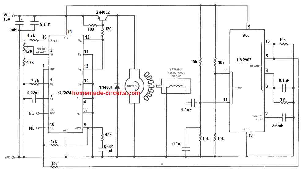
The above diagram shows a basic PWM motor control circuit using the IC LM3524. The design additionally incorporates a sensor based feedback control through the IC LM2907.
A small magnet is attached with the motor shaft, such that during the rotations, the magnet goes past closely to an iron core pickup coil transformer.
The mechanism, causes the rotating magnet to induce a sharp electrical pulse in the pickup coil, which is used by the LM2907 as a trigger input and appropriately processed as the feedback control pulse to the LM3524 IC.
The feedback system ensures that the speed of the once set can never deviate from the set point, providing a precise control of the speed. The pot at pin#2 of the LM3524 is used for controlling the speed of the motor.
Sensorless Control, Without Motor Back EMF
The next LM3525 PWM speed control design allows the feedback control without incorporating a complex tachometer mechanism, or cumbersome sensor arrangements as implemented in the previous design.
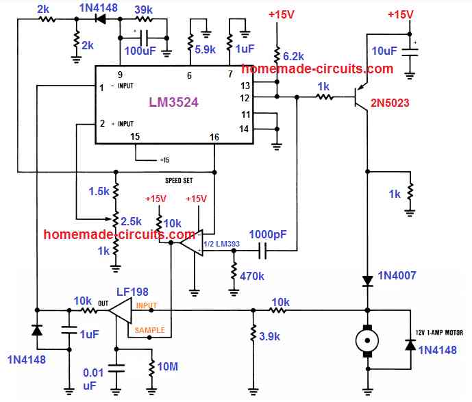
Here, the back EMF from the motor is utilized as the feedback signal and applied to the input of the IC LF198.
In case the speed tends to rise beyond the set level, the LF198 compares the rising EMF signal with the sample reference signal from the LM393 output.
The resulting output is sent to the error amplifier of the IC LM3524 for the necessary processing of the output PWM to the driver transistors.
The controlled PWM due to this sensor-less feedback through the back EMF ultimately enables the motor to remain precisely fixed at a correct speed, as adjusted by the pin#2 potentiometer.
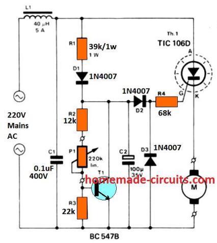


Questions & Answers
The same circuit can be used for your application too. Just make sure the IC circuit gets around 12V supply derived from the 90V supply.
The motor can be connected with the 90V supply directly in the manner shown in the diagram.
HI,
You may misunderstand me… You know my motor have 18k rpm in no load and about 5k rpm when connected to 4v 3 amp battery and about 10k rpm on 6v 4.5ah battery.
For got about my stupid TDA7274 circuit. its giving me about 700-900 rpm to me which is not any value and its not giving me any airflow that can I feel from 12" far.
So I want to through the Circuit to the dustbin as its useless and the IC is getting about too many hotter, you can feel that it can cook your rise in 10 minutes. So I am pretty sure the circuit will not last long and it can be make any damage as its hotting up.
Now I want your help, I hope you seen my motor and which fan I connected (s10.postimg.org/7da0t1c6h/2013_07_16_02_25_04.jpg)
Please give me any circuit that can drive my motor with this fan (load) at 2-4 k rpm. I found that my motor is stable on this RPM but it getting hot if I it go to more that 5k rpm.
Please don't leave me alone here. want your help,
Awaiting to hear from you.
Regards,
MD
The motor maximum RPM will be as per it's rated specification, it cannot be increased beyond that.
A speed controller will only reduce the RPM from the specified high value to the lower levels.
Anyway, you may try the circuit given at the bottom of this page:
https://www.homemade-circuits.com/2011/12/constant-torque-dc-motor-speed.html
n-channel, rated higher than your motor Voltage and Current specs
The power supply rating should have a voltage rating exactly matching to the load……current is immaterial, but should be higher than the load, if it's lower, the voltage will drop.
The mosfet can be anything…just needs to be rated at least twice to the load rating, if it's higher no issues, but preferably shouldn't be lower.
yes, will do.
Could you use a 50k pot instead with out changing any other components? Thanks
?? Sorry can you explain
For confirmed results the cap C1 may be replaced with a 0.01uF if a 50k pot is used. rest will remain as is.
correction: 50k pot will not need any mods in the circuit….
It's my pleasure!
You are most welcome!
I couldn't understand the relation between heatsink mounting and motor positive connection.
for zero to 100% speed control you will have to make the following circuit, the above circuit will not provide 100% control:
4.bp.blogspot.com/-G-E1CvLaU4U/UOfhAH6C0ZI/AAAAAAAACas/nsaEsevlY6k/s1600/reverse%20forward%20dc%20motor%20speed%20controller%20circuit.jpg
Thanks Buddy:) appreciate your enthusiasm!
The 100% constant torque would be a better option as it presents more efficient PWM control over the motor, here's the article which are to referring:
https://www.homemade-circuits.com/2011/12/constant-torque-dc-motor-speed.html
Regards!
So much SWAG! 🙂
Im trying to build a PWM controller for a dc motor that runs a fluid pump. I know it would need 0-100% control, but I also think that your constant torque circuit would be better. (since i need to deliver exact amounts of fluid) However the constant torque circuit you provided shows a bi-directional motor and I could not follow your text instructions for making it single direction. I would like to be able to adjust frequency, and pulse width. Circuit will a regulated 8v from the batterypack/power supply. Can you maybe point me to a good instructions page to build for this? (motor "on time" will be determined by a lookup table using a micro processor, but thats a whole nother issue)
Thanks JC,
Please refer to the following diagram, you can try this design:
1.bp.blogspot.com/-jONLYQ8Ehro/UkD_gzAjA-I/AAAAAAAAFSk/nt6vxMDF9RU/s1600/ELC%20circuit.png
Connect your motor across the drain and positive of the circuit…please ignore the bridge rectifier it's not meant for us.
The shown PNP transistor is BC557 and not BC547 as wrongly given in the diagram.
The pot at pin5 of IC2 can be used for controlling the speed,
The mosfet can be replaced by a power transistor, if desired. In this case use ordinary 555 IC, and not 7555.
Thank you for you speedy response. I would have commented earlier but i was waiting for an email telling me you responded. (never came) could you please verify for me the value of R4. i believe that should be 2k ohms.
also one other thing, From what i gather, adjusting pot at pin 5 will control the duty cycle, but could you please explain how i would go about adjusting the frequency should i need to. I have built your other PWM circuit and it worked great. (using one 555ic)
I remember a time back when i was in air force tech school when i could of done all this with my eyes closed. they were very thourough. its amazing to me how only in a few years i could forget so much!
My replies here are supposed to reach the commentor in their email IDs, you should find these discussions in your email inbox, according to me.
Although the frequency has no relevance to the motor speeds, it can be controlled by varying R1 or the 180k resistor value.
I am sure the discussions here will help you to restore all you had learned back:)
use IRF540 mosfet and 15amp power supply, this will drive the motor with the specified power.
Connect the mosfet leads in parallel, use separate resistors for the gates.
And do not short circuit the positive with drain, this will instantly blow off the mosfets.
In the diagram no resistor is indicated, but you can use 100ohms with the gates, will be OK.
4amp will not give you 15amp….you will need a 15amp supply for that.
the pot control is for speed control, it has no relation with current….use a 2amp fixed current power-supply for getting the required current restriction.
Is this circuit 0 to 100% duty cycle? I want the frequency to be constant 60 Hz. How would I do that?
Using this formula? F = 1.44(VR1*C1)
Based on your circuit you put 100k for vr1 and 0.1u for c1. Frequency will be 0.0144 hz?
No it's only from 50% to 100%, and frequency will not be constant if duty cycle is changed for this circuit.
Hai, I bought one 12v dc motor. I connected it directly to the 12v adapter. Then the motor is running in a pulse mode. Means like clocks seconds needle moving. running, stopped, running, stoped. like that. When i asked abt this to the shop man, he told that the motor got damaged due to directly connected to the 12v power supply, a 12v motor should not directly connected to a 12v power supply, It should connected through shunt (resistor). But he dont know what resistor have to put.
Could u tell me, is that correct which he told?? and wat resistor i have to connect between the motor and the power supply if I want to connect the motor directly to the 12v power supply?
Now I bought another motor which is rated 12v ,0.28A. I like to connect this motor to ur above circuit. so still do I need a Shunt (resistor)?? and wat value, rated mosfet I can use for ur above circuit?
Hi, that's completely rubbish…if the motor is specified to run at 12V it can be safely connected with any 12V supply (regardless of the amp rating of the supply).
shunt resistor may be required for protecting the power supply (SMPS) from the back emf that may be generated by the motor…. so its the power supply that may need protection with a shunt, not the motor.
The above may be true only with big heavy duty motors only….not in your case.
Thanks for the clarification… so the shop man cheated me by giving a damaged motor itseems :-(… Now am having a 12v, 0.28A DC motor. I like to use this motor in ur above circuit. so Could u tell me that wat mosfet i can use for this??
mosfet may not be necessary, you can use a TIP122 in its place and connect the motor as indicated (across collector and positive)
hi,
what power supply and mosfet should i use for a 180 to 220vdc motor, as well as adisplay in the circuit to show the motor rpm
An IRF840 mosfet could be tried, power supply should be DC and as per the maximum rating of the motor….for RPM you'll have to procure a ready made RPM meter and integrate it with the motor.
Sir can i use two Motor in parallel
yes you can do it if the total amp is within the max rating of the mosfet
Dear Sir,
I am a beginner.
Can I use the above circuit for my treadmill with 180V 6A 4200 RPM DC Motor. I would like to use the mill only for normal walking of about 30 to 45 minutes in normal speed.
Can I reduce the RPM to my desired speed (only for walking with speed of 4 to 6 KM/hour) using the above circuit. If I use the POT, what would be the changes in the RPM when the POT gets in to its maximum and minimum positions. If I can use the above circuit, pl suggest me the appropriate MOFSET for the above load.
I went through all your reply and it is interesting and valuable. I really appreciate your patience and commitment.
Sir, my thanks to you in advance
Shine K P
Thank you dear Shine!
yes, according to me you can use the above circuit for your said application.
The maximum achievable speed is near 95% and the minimum is near 5% so it's pretty efficient with its control spces.
You can use IRF840 as the mosfet.
Dear Sir,
Sorry for bothering you…..
I tried this circuit but in between got stuck because, I am not finding any way to bring 12V dc to IC 555 as my rectified DC is 180V, which I am using for motor, in the board. I believe, I cannot connect LM7812 directly to this volt. Can you please help me on this?
Thanks & regards,
Shine K P
Dear Shine you can use any standard 220V to 12V AC/DC SMPS power supply for this….you can get it in the local market,
even your phone charger will work for the time being.
Dear Sir,
Thank you for your mail…
Sir, then I have to connect Ground of 180V DC supply to Drain pin of MOFSET. Am I right sir?
Regards,
Shine K P
Dear shine,
the drain will connect with the (-) of the motor, please see the diagram above.
The (-) of the 180V will become common with the (-) of the 12V supply…..the motor (+) will connect with the (+) of the 180V supply
Dear sir,
Sorry…..
Now I understood….
Thank you very much…
Regards,
Shine K P
Sorry sir…it was my mistake……
Dear Sir,
I tried this
1)Motor didn't run when the power on
2)When I turned the POT, it started running but immediately 555 got burned and MOFSET as well LM7812 also got hot.
3)Even though the smoke was comming from 555 motor was running.
4)I checked the circuit and found no short circuit.
Sir, what could be cause for this? Can you pl advise me…..
Thanks & Regards,
Shine K P
Dear Shine,
I recommended using a separate 12V AC/DC adapter for powering the IC stage…not a 7812 IC so please build it again and power it as suggested.
also connect a 6amp rectifier diode right across the motor coil in order to safeguard the fet from motor back emfs.,
Dear Sir,
I didn't get 12V AC/DC Adapter but got 15V AC/DC from my nearest shop. That is the reason, I used 7812 to get the regulated 12V DC to IC.
1)Should I use 12 AC/Dc adapter and remove 7812?
2)Sir, I joined both -ves (180 and 12) and grounded wherever it is mentioned in the circuit, even to source of MOFSET. Hope it is correct.
3)Offcourse, I can connect protector diode and will try again.
Thanks & Regards,
Shine K P
Dear shine,
yes, 7812 with 15V input is perfectly fine, and making the negatives common along with the fet source is also perfect….I think attaching the diodes across the motor should solve the problem.
Dear Sir,
I connected the 6A4 diode across the motor, now IC and 7812 are okay but MOFSET is getting hot. I think, the MOFSET got damaged while it got heated last time.Now motor is running in its full speed. No control on POT and MOFSET is getting hot also.I put heat sink for MOFSET and 7812. I noticed, even without inserting 555, motor is running in its full speed.I checked the POT and it is working fine. Let me change the MOFSET. I would require your hep sir….sorry for bothering you.
Regards,
Shine K P
Dear Shine, if without IC the motor is running that surely indicates a faulty mosfet…try using two mosfets in parallel for ensuring better safety to the mosfet and reducing heat dissipation
Dear Sir,
Thank you….noted your suggestion. Let me try this also. Can you please advise me on below
1)PIN 7 of 555 will be connected to GATES of two MOSFETs seperatly. Do I need to need to add 10k again? ie Do i need to add 10k before each GATE?
2)DRAIN of two MOSFETs will be joined together and connected to -ve of motor
3)SOURCE of two MOSFETs will be grounded.
Am I right sir?
Regards,
Shine K P
Dear Shine, the 10k need not be repeated, pin7 needs to be connected with each mosfet gates via separate 22 ohm resistors.
next, drains will join together and connect with the motor negative, sources will join together and connect with the ground
Dear Sir,
Thanks….Let me try…
Regards,
Shine K P