A very simple darkness activated or night activated PIR lamp circuit project has been explained in the following article. Further in the article we also learn how to upgrade this circuit with an additional emergency lamp facility.
This darkness activated PIR lamp will work as I have explained below:
It will remain deactivated or disabled during day time, as long sufficient ambient light is available around the LDR sensor of the circuit.
The circuit will be enabled as soon as the darkness level becomes adequately low, or when night time sets in.
In this position if a human being is detected within the detecting range of the PIR lens, the PIR lamp is instantly switched ON automatically.
The lamp remains switched ON as long as the human presence remains active in the range. The lamp is automatically turned OFF when the human being leaves the detection area of the PIR.
Circuit Description
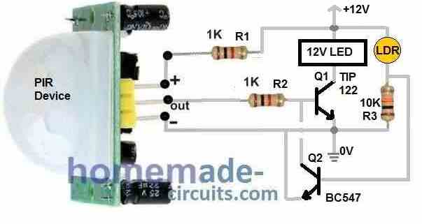
Referring to the circuit diagram below, a PIR module becomes the main component of this night activated PIR lamp design.
Parts List
- Resistors 1/4 watt CFR
- 1K = 2nos
- 10K = 1no
- LDR = 1no
- Semiconductors
- Transistor TIP122 = 1no
- Transistor BC547 = 1no
- PIR module = 1no
- 12V LED Lamp = 1
As you can see, the PIR is wired in a very unconventional way. In this setup the PIR is not supplied with a 5V regulated supply, rather supplied directly from a 12V DC through a 1K resistor.
This innovative idea was exclusively discovered by me and it allows the PIR module to work very effectively.
While experimenting I found that with a normal 5V DC through a 7805 circuit, the PIR performance is quite erratic and unpredictable.
To eliminate this problem, I came up with the above setup after a lot of experimentation. Here, I completely eliminated the 7805 section and simply used a 1K series resistor to regulate the input DC. This idea allowed the PIR performance to be very stable, without hiccups.
Now let's return to our main topic and understand how this darkness activated PIR lamp actually works.
There are basically two stages in this design. One is the PIR lamp using the resistors R1, R2, transistor Q1 and the LED lamp. The other stage is the darkness detector stage comprising of the transistor Q1, LDR and the resistor R3.
During night time when the ambient light on the LDR is sufficiently low, the BC547 remains switched OFF. Therefore the transistor Q2 which is a TIP122 LED driver is able to remain in the active and standby position.
In this position, as soon as the PIR detects a human presence within the range, it activates and supplies the required base voltage to Q1 and turns it ON, which then turns ON the LED lamp.
In this way, during night time, the PIR LED lamp is able to automatically switch ON and OFF, depending on the presence or absence of a human being within the detection range.
During day time, when there's adequate light on the LDR, the BC547 Q2 is turned ON, which connects the base of the TIP122 Q1 to ground.
This completely disables the Q1 and it is unable to switch ON the LED lamp regardless of whether the PIR detects a human presence or not.
Power Supply and LED Lamp
The power supply to the above explained darkness activated PIR lamp circuit can be derived from a standard 12V transformer based power supply or an SMPS 12V power supply.
The LED lamp can be any type of 12V DC LED lamp.
The power supply current must be selected as per the wattage specifications of the LED lamp.
LED Lamp Power = Voltage x Current
Assuming the power of the lamp is 10 watt, then the LED current rating will be.
Power = 12 x Current
10 = 12 x Current
Current = 10 / 12 = 0.833 Amps or simply 900 mA
Thus, as per the above calculations, the power supply can be rated at 12V, 1 Amp.
Upgrading to Darkness Activated PIR Emergency Lamp Circuit
The above explained night activated PIR lamp circuit can be further enhanced by adding an emergency lamp facility to the design.
The following figure shows the complete circuit diagram.
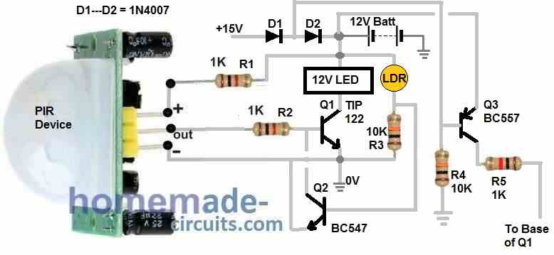
Referring to the above diagram, the emergency lamp upgrade is added by including the parts D1, D2, the battery, the Q3 transistor, and the resistors R4 and R5.
The diodes D1 and D2 does a dual function. It causes the 15V to drop to 13.8V for providing a safe charging voltage to the 12V Lead acid battery. Along with this the D1 and D2 keep the Q3 base isolated from the 12 battery.
As long as the electric utility power is available, the voltage after D1 keeps the transistor Q4 disabled and switched OFF.
The voltage after D2 provides the DC for the circuit operation and also to charge the attached 12 V battery.
In this situation the darkness activated PIR circuit is able to work normally as explained in our earlier section.
However, in an event when the mains utility power fails, the base voltage of Q4 disappears, which allows it to switch ON instantly via R4. This toggles ON the emergency lamp feature of the circuit.
With Q4 switched ON causes the battery voltage to reach the base of Q1 via R5.
This allows the transistor Q1 to switch ON permanently and turn ON the LED lamp.
The LED lamp now illuminates through the battery power as long as the grid mains is unavailable. When the utility power is restored, Q4 is switched OFF causing the Q1 to return to its normal position. Now Q1 can respond to the PIR signals and the signals from the darkness sensor stage. This circuit returns to its original condition where it can simply work like a night activated PIR lamp circuit.


Comments
Dear Swagatam,
I am very grateful for the darkness activated PIR lamp circuit. I have been struggling to create such a circuit from scratch using minimum components, and yours is so easy! It even works with a 3.7v lithium battery and 5v solar panel. I use the output from the PIR to trigger a transmitter/receiver pair
KIndest Regards
John Renwick
You are most welcome John, Glad it worked for you. Thanks for updating the information.
Hello swagatam; How many seconds does it stay on when the medicine 122 PIR circuit is active? There is no capacitor in the circuit. Respects
Hi Adnan,
The delay is determined by the trimpot inside the PIR module. You can adjust this trimpot to set the delay as per your requirements.
If you remove the plastic lense of the sensor there is a position to install the night time ldr feature inside the PIR sensor!
The rest of the load driver and emergency feature is ok.
Yes, that’s correct. Thanks for your useful feedback.
You’re welcome. I am a retired electronic engineer but I keep an eye on things still. I enjoy seeing your ideas, most of them are very useful, keep up the good work!
Glad to know about you! Appreciate your kind feedback!