In this article I have explained a car side marker modification which enables it to respond to the existing turn signal pulses and flash in tandem with the turn signal flashing. The idea was requested by Mr. Jerry Klein.
Technical Specifications
I have a 1990 automobile which I believe does not have very sophisticated circuitry controlling the direction signals /driving lights and side markers.
This should work in my favor when converting to LEDs. I am currently using a simple wiring mod that has worked successfully for 20 years. I cut the side marker's ground wire and reconnected it to the turning signal lead off the direction signal /driving lights.
The driving lights are dual filament 1157 and the side markers are single filament 158. I love they way they work and would like to convert them with my modification to LEDs.
The side markers flash on when the driving lights are off; they flash off when the driving lights are on.
I quickly realized that this will not work because the light bulbs are working with reversing polarity and therefore I will need a more managed solution.
I think the solution is running the side markers with constant hot lead and controlling the blinking off or blinking on with some kind of control circuit on the side marker's ground.
I would also like to connect up my rear side markers another 158 bulb to the same circuit.
I am not a brain when it comes to circuitry but I have done some simple tasks with relays and am good with a soldering gun.
I wanted to have my 100W 7 amp fog lights work off a dimmer so that I could tune them in to the exact lighting requirements. I purchased a boat dimmer unit that could handle the current which worked with a taping pulse switch for on off and hold for cycling brightness.
Had I known about your before I could have saved money with your circuit design. Boat parts are synonyms with big bucks.
I can buy the required parts and wire them up as directed. I have looked through your blogs and have not been able to find the exact solution.
Can you please help me with this circuit design and parts list. I would have to know what wire goes to what post on each component.
I could not figure out how to join your blog and therefore this email.The enclosed chart represents the current wiring configuration of my car.
After changing to an LED compatible flashing unit, everything is working correctly.
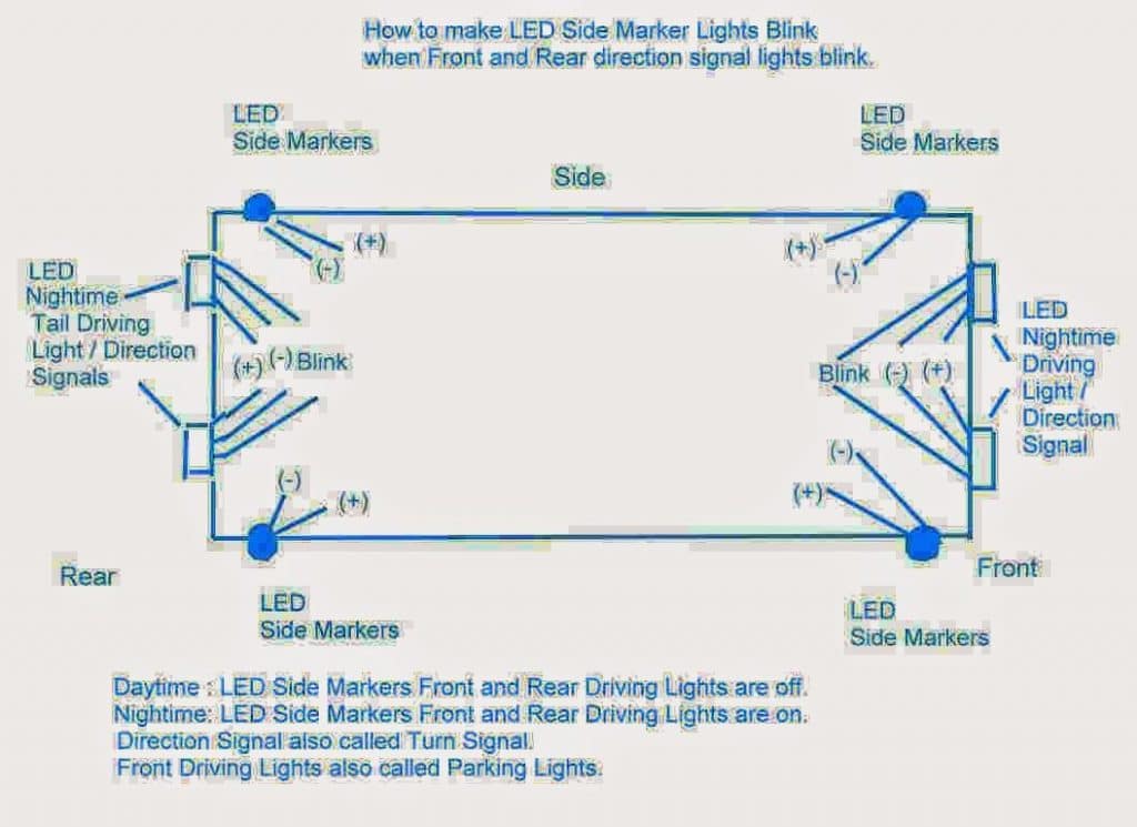
The chart shows four LED Side Markers they are single function bulbs: off during the daytime; on at night.
They do not blink.The front and rear lights LED bulbs have dual function: two circuits One line controls night / on and a day / off. The other line controls the turn signal blinking function.
We are only concerned with the turn signal function.
I would like the front and rear drivers side LED Markers to blink when the drivers side Front and Rear turn lights are blinking.I would like the front and rear passenger side LED Markers to blink when the passenger side Front and Rear turn lights are blinking.
The project is to create two identical circuits for the car's left and right turn signals.
The circuit taps into the blink turn signal line to determine when it is pulsing causing the car's turning light to blink. The circuit will then blink the corresponding front LED Side Marker.
A wire will be run from the front LED Side Markers to the rear LED Side Markers giving them the same functionality.
During the day, it blinks the LED Side Markers ON.At night, since the LED Side Markers are illuminated the circuit reverses and blinks the LED Side Markers OFF.
Regards
The Design
As per the requirement, the existing side marker lights which are designed to stay ON during night and OFF during day are expected to blink in response to the turn signals lamp switching.
It means the intended customization should be designed such that it blinks the side markers by alternately cutting off the supply during day time, and by alternately applying power during night time, these are two different modes which are required to induce the desired flashing effect on the specified side markers whenever the turn signals are switched ON.
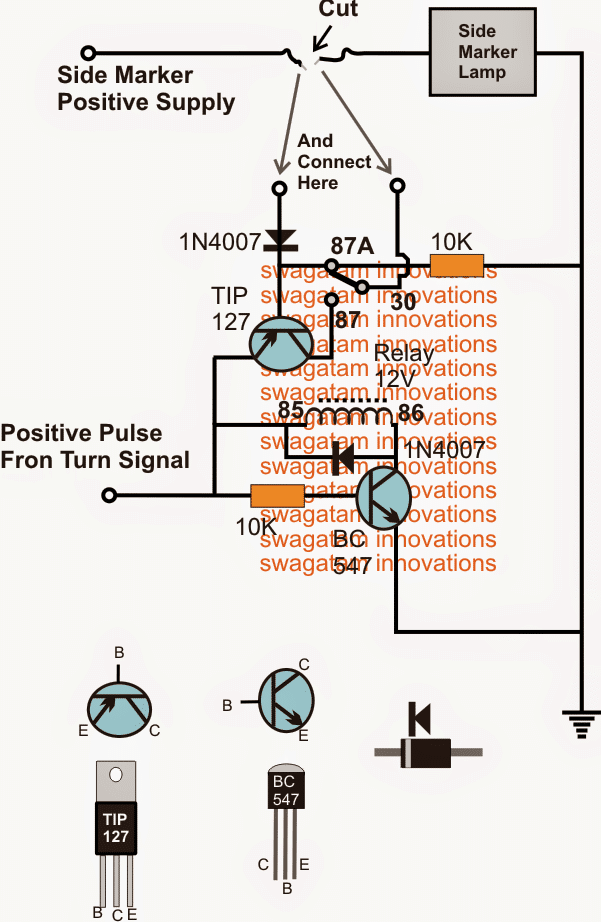
Referring to the diagram, the positive line of the existing side marker needs to be cut and then joined across the two shown points of the recommended circuit.
The design can be understood as follows:
Once the above modification is done, during night, the side marker positive line carrying the positive supply would normally keep the lamp switched ON through the 1N4007 diode, and the N/C contact/pole of the relay.
Now if the turn signal lamp is switched ON, the relay driver BC547 would start pulsing in response to the acquired signals from the turn signal source.
This pulsing would alternately break the positive line of the side marker causing it to blink. The TIP127 in this situation would have no effect on the N/O contact of the relay due to the positive feed at its base from the side marker supply.
However during night time, the positive line of the side marker would have no positive supply, in this situation whenever the relay would be activated in response to the turn signal pulse, the TIP127 also being activated (via base 10k resistor) would pass the positive from the turn signal feed to the side marker via the N/O contact of the blinking relay....this would make sure the side markers yet again blink as proposed in the above request.
Modifying to Flash According to Turn Signals
The following figure shows how to modify the above car side marker further such that it always flashes in accordance with the turn signal pulses:
Circuit Diagram
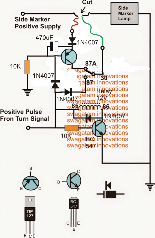
The 470uF makes sure that the PNP TIP127 remains completely disabled while the turn signal is operating.


Comments
Hello Swagatam.
How would I modify your second schematic (the one that flashes side markers in sync with the turn signals in both day and night modes) to replace the mechanical relay with a TIP127?
My LED side marker draws 0.75 W. So, it’s within the capacity of the TIP127.
Thank you,
Gary
Hello G. Hauck,
Implementing twin function using transistors only looks difficult. Might not be possible. The twin function is as per the following specifications:
During the day, it blinks the LED Side Markers ON. At night, since the LED Side Markers are illuminated the circuit reverses and blinks the LED Side Markers OFF.
Funny thing. I made this modification to the lighting on my 1973 Ford Falcon XB, in 1977!!
No, I did not use LEDS (yes, they were available but nowhere near bright enough, and way too expensive!)
The car did not have side marker lights, and after a near miss (at night) where another car failed to give way, I decided side lights would be a good idea.
I bought a pair of Toyota side marker lights. Coincidentally, they had two wires, none being grounded.
So I connected the +12Volt wire to the car’s parking light circuit, and grounded the other wire. Yes. They worked as intended (came on with the parking lights). Then I disconnected the ground wire, and connected that to the +12Volt side of the front indicator on the same side. Now, it it was day time, the side lights would flash with the indicators as they had +12 Volts fromt the indicator, and ground via the (normally) + side of the parking lights (not on at this stage) through all the parking lights in parrallel, to ground.
If I switch the parking lights on, the side lights came on – now grounding through the (off) indicators. When I used the flashing indicators with the parking lights on, the side lights flashed – but as everyone has said, they flashed out of time with the indicators. That was actually an advantage as it bought attention to the fact the indicators were flashing.
It did, however result in a failure at registralion time, as the inspector said the indicators must all flash in sync. However, when the final inspector double checked I had the presence of mind to make sure the parking lights were off, so they all flashed in sync. It passed. The final inspector guy just scrubbed out the original failure advice.
I also “invented” a brake light failure circuit using only a normally closed reed switch, a coil of thick wire and a red dashboard indicator light.
Method: Connect a wire from the output of the brake light switch to the +12Volt side of the dashboard light. The other side of the light connect to one side of the reed switch. Connect the other side of the reed switch to gound. Wind several turns of the thick wire around the reed switch. Connect the thick wire coil between the brake light switch and the wire going to the brake lights.
Now when you press the brake pedal, the current drawn by the brake lights energises the reed switch (via the coil). The reed switch opens. So the warning light on the dash doesn’t come on as it has no ground. If the brake lights are blown or disconnected, the reed switch will not open as there is no current through the coil. So the warning light on the dash comes on.
One thing I found is that originally there was sufficient current through the coil to energise the reed switch if only one brake light failed. So by reducing the number of turns of with around the reed switch I could easily make the system work if only one light (or both) failed. Yes, the circuit introduced a resistance to the brake light circuit, but I found I only needed one layer of the wire around thr reed switch to make it work. Not much resistance at all.
I do have a theory about inventions occuring at several placed around the world at the same time. Not so possible now with the internet.
Thank you for your detailed explanation and efforts, appreciate it very much, hope the readers will find it useful.
Yes I believe I actually do follow you on that.
Would the collector of the BC547 still go over to the turn signal source as well as the base of the new TIP127/10k or only the TIP27/10k? (The diode across the coil could be eliminated if that line was still needed)
Thx
for this new design which will use only BJTs and no relay, the BC547 collector will connect solely with the base of the second TIP127 through a 10K resistor. The previously indicated relay coil along with the diode will no longer be required and could be eliminated, and the collector of the BC547 only hooked up with the base of mentioned TIP127
Hello
Stumbled across this thread doing a little research as I consider changing my car lights over to LEDs. It's wired from the factory (GM) such that the front side marker lights flash with the front turn signals and opposite (ground reverses) when the running lights are on. Since the ground reverses, I can't run LEDs on the front and sides.
I can change the wiring and add in a relay (much like shown above) but was just wondering, if the side marker lights are smallish LEDs and only drawing 50mA, is there no way of making them work without using the relay?
More curious than anything
H
Hello, you can possibly try the following idea:
Take another TIP127 BJT, connect its emitter with the emitter of the existing TIP127, base with the collector of BC547 through a 10K resistor, and then use separate diodes (1N4007) with the collectors of these two TIP127 such that their anodes go to the respective collectors, and the cathodes join together and connect with the side marker LED's anode, while the cathode of the LED goes to the ground, I hope you understood the connections…
If it discharges to fast the marker starts turning on before the next blink. With the second relay the capacitor was to discharge enough to release relay. Giving it enough time to not effect the blinker and an instant on to marker light.
OK great, in that case you can consider of changing the TIP127 with a smaller transistor such as a 8550 or 2N2907 for making the design more economical and compact
I tried different combinations of capacitors and resistors which helped. But was unable to get the instant one and off I was looking for. So I used your circuit but used the TIP127 to control a second relay. Works perfect.
Thank You for all your help
Jon
oh, that looks awkward and an overkill, anyway if you are satisfied then it's fine….
you can try connecting a 1K resistor parallel with the side marker lamp and see if that discharges the cap quickly…
I assemble the circuit today. Blinks as correctly. Only issue I'm seeing is marker light recovery to on. Marker on after blinker is turned off it fades in to full brightness. Would a smaller resistor or capacitor help lessen the fade in time? Is there a way to have it turn back on after voltage reaches a certain threshold of approximately 10 volts or higher.
yes that's' possible, reducing the 470uF to some lower value, say to 220uF or 100uF will correct the issue
Looks like it would work great. I'll assemble it tomorrow and give it a try. Thank you.
you are welcome!
As Abel Labour stated earlier it does flash out of time. Only with marker lights on at night. During the day it is in time with the other turn signals. Since it uses the turn signal input at night, it turns off when the other lights turn on. Any thoughts on what to add to the circuit to correct this?
yes the initial circuit was designed to operate in the opposite way at night as per the original request
I have updated a new diagram, check if that works as per your specifications
OK thanks, I am glad it's now working for you as per the expectation.
I actually got it up to a 1000K resistor for each light. From +12vdc wire to light then to battery ground.
I put a 2.2k resistor from the positive side of light to ground and it fixed it. So pin 30 of relay to ground. Should be ok?
I completed this project. It works but I have one small issue. I'm using premade 8 LED lights as marker lights. It works great during the day. At night marker on and when the turn signal flashes, it glows. There is a faint glow of the LED lights. They don't turn completely off. Any ideas?
Please add a couple of 1N4007 diodes in series with the LED positive line and check if that solves the problem…
Thank you!
Greetings
I am trying to use this circuit to make my side marker lamp to flash on and off when the turn signal lamp are activated. I am using LED light bulbs. One thing that I noticed when I analyzed this circuit is that the side marker lamp will be fashing out of synchronism with the turn signal lamp. I will like to have everything flashing at the same time and I am wondering if I can connect the turn signal light bulb at the point 87 of the circuit. I think this modification will work but I would like to have your opinion. Also I will like to know what will happen if I change the value of the two resistor. I am planing to use 2 variable potentiometers (20k ohms).
Regards
Both the lamps will flash in sync according to the design, can you tell me why do you think it won't?
yes you can connect the turn signal lamp with 87 which is the N/O of the relay.
the 10K value is dependent on the relay coil current…so you can tailor the value accordingly, however a pot is not recommended and is not necessary, it must be a fixed resistor.
Sir any modification needed or we just need to adjust the resistance and led to drive
on 6 volt.
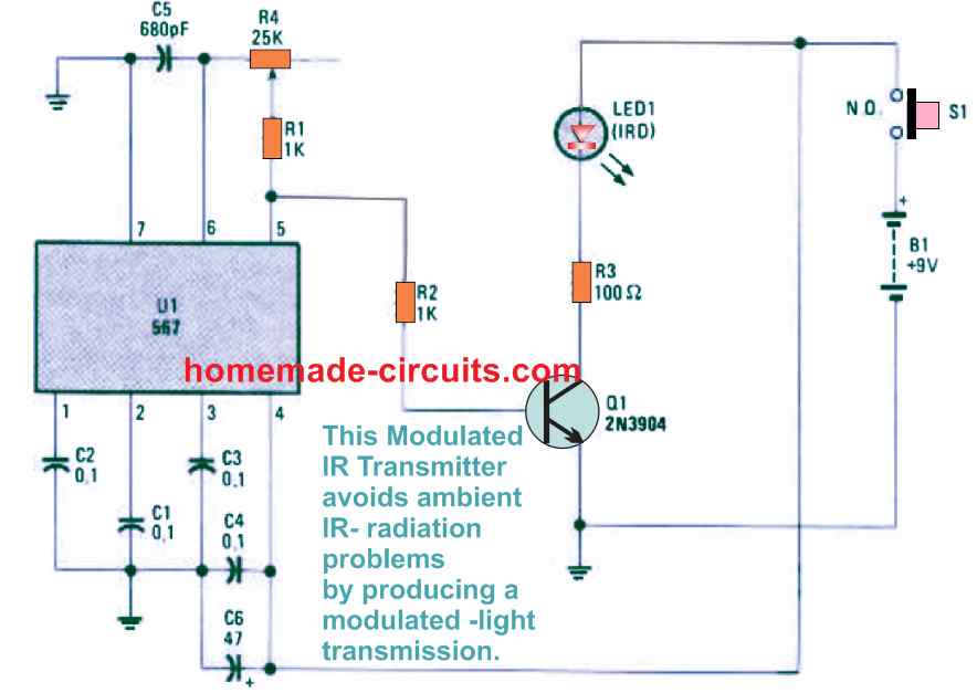
Simple PIR Controlled LED Lamp Circuit
1.bp.blogspot.com/-MlL3YrsADGU/U4Gg728Ct4I/AAAAAAAAG-s/qr5pq95RMKg/s1600/PIR+LED+driver+circuit.png
Thank you 🙂
Ram, no modifications would be required in the circuit, for the LEDs just use 2 LEDs in each string without any resistors.
Hi Swagatam
Would you please post the "enclosed chart" which Mr. Jerry Klien is referring in his request. I am finding it bit difficult to understand his request.
What are side markers? Does he mean the side indicator lamps with LEDs?
Your design is quite simple and straight-forward, it should definitely work.
Let's see how Mr. Jerry gets it working.
Hi Abu-Hafss,
I have updated the diagram, please check it out. The blue circles are the side marker lamps