• Skip to main content
  • Skip to primary sidebar

Homemade Circuit Projects

Need circuit help? Post them in the comments! I've answered over 50,000!

Blog | Categories | About | Contact | Calculators-online
You are here: Home / Lamps and Lights / Converting Ordinary Rice Bulb String Light to LED String Light

Converting Ordinary Rice Bulb String Light to LED String Light

Last Updated on September 8, 2020 by Swagatam 12 Comments

In this post we study how to convert a rice bulb string light into an LED string light using some simply circuit modification.

Circuit Concept

Whether it's during a  festive occasion or for mere decoration purpose, the Chinese rice bulb flashing lights have become  hugely popular nowadays

These can be seen as multiple interlaced wire strings consisting of many different colored minute rice shaped bulbs which produce variety of lighting patterns when switched ON. Though these generate stunningly beautiful illuminations, are not much reliable.

The above explained types of rice bulb circuits incorporate  triacs, controlled by an embedded automatic sequencing chip (COB) circuit.

How Rice Bulb Strings Work

There may be  three, four or five channels controlled by the chip circuit terminated through tiny low current triacs. These triacs are high voltage, low current types, meaning these can handle upto 300 or 400 volts but cannot withstand more than say 10 to 20 mA of current

The bulb strings which are operated through these triacs are all tied up in series, therefore they present high voltage across these triacs, but since they have a very high filament resistance, the current consumption is very low. The criteria perfectly match the triac ratings.

However being in series means if any of the bulb fuses, the entire string shuts off.

Another issue with such products is there low quality wires which often tend to break spoiling the operation of the entire unit.

Though the circuit box often remains in working condition the wired elements tend to get damaged, torn, blown of etc.

Recently one of the keen readers of this blog Mr. PP suggested the use of LEDs in place of bulbs which according to him could make the lights more reliable and long lasting and also more beautiful looking.

Replacing Rice Bulbs with LEDs

LEDs can be used in place of the filament bulb, however these devices have entirely different operating characteristics. First of all they cannot restrict current like filament bulbs, meaning if directly replaced with the bulbs, both the triac and the LEDs will get destroyed instantly.

The above issue can be solved by employing a series capacitor reactance for limiting the current to 20 mA or so.

Normally, on opening the circuit box we would see small transistor shaped components lined up in a row terminating the corresponding string's wire ends.

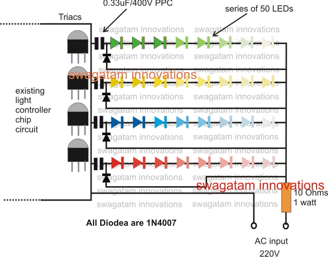
Simply by adding series high voltage capacitors with the subsequent LEDs, the bulbs probably can be replaced with LED strings.

The following diagram shows how it can be done. The idea pretty straightforward  just connect the LEDs in series along with the shown capacitors, hopefully all would start flashing and running instantly when switched ON.

The procedure is based on my assumptions and has not been tested practically so kindly be careful with it if you are actually trying this idea practically.........

riceledbulbcircuitstring 1

You'll also like:

  • 1.  Neon Lamps – Working and Application Circuits
  • 2.  Ceiling LED Lamp Driver Circuit
  • 3.  AC Light Dimmer Circuit
  • 4.  Simple PIR LED Lamp Circuit
  • 5.  Musical Christmas Decoration Light Circuit
  • 6.  Compatible LED Tube Light Circuit for Standard Ballast Fixtures

About Swagatam

I am an electronics engineer with over 15 years of hands-on experience. I am passionate about inventing, designing electronic circuits and PCBs, and helping hobbyists bring their projects to life. That is why I founded homemade-circuits.com, a website where I share innovative circuit ideas and tutorials. Have a circuit related question? Leave a comment.... I guarantee a reply!

Previous Post: « How to Illuminate 1 Watt LEDs with Cell Phone Charger
Next Post: Making a Cell Phone Controlled Remote Bell Circuit »

Reader Interactions

Comments

  1. Pouynn says

    August 10, 2023 at 11:26 pm

    Wow, these landscape lighting installers are very talented! They have completely transformed my outdoor space into a magical oasis. The attention to detail and the stunning designs they created exceeded my expectations. Highly recommend their services for anyone looking to elevate their landscape with beautiful lighting.

    Reply
  2. gururaj acharya says

    November 15, 2020 at 6:42 pm

    Does this circuit really work , has anyone tried it ?

    Reply
  3. X.D . Pereira says

    September 30, 2019 at 6:37 pm

    Any idea how two-wire controllers produce patterns, Mr. Swagatam? The power supply is 31 v and the two wires from the led strings go to 2 pins on the IC.

    Reply
    • Swagatam says

      September 30, 2019 at 7:41 pm

      Hello XD, you will have to confirm the polarity of the wires and only then you may be able to connect it to the power supply safely. Check which wire among the two connects probably with a capacitor negative lead directly, this will inform us regarding the negative wire, so the other one could be the positive..

      Reply
      • X.D. Pereira says

        September 30, 2019 at 9:15 pm

        Thank you for your reply Swagatam.
        Actually I want to know how the two-wire system works . The terminals are marked + and – only. Voltage is 31, but 8 different patterns can be selected.
        The 8 Functions
        1. Combination
        2. In Waves
        3. Steady On
        4. Slow Glow
        5. Chasing
        6. Slow FAde
        7. Twinkle
        8. Steady On

        Reply
        • Swagatam says

          October 1, 2019 at 6:42 am

          Hi XD,
          The sequencing is controlled by the complex programming code of the IC.

          The two wire act as the supply input and also the output for the bulbs. The series bulbs drop the voltage and current for the IC, and the IC then operates by varying the sequences alternately by making and breaking the current to ground wire.

          Reply
  4. Pradeep Almeida says

    May 4, 2017 at 1:44 pm

    If I use 10leds each channel after replacing BT 136 will I able put 1w LEDs or give me a suggestion to alter this cct

    Reply
    • Swagatam says

      May 5, 2017 at 5:51 am

      1 watt LED could be used if the 0.33uF is replaced with a 2uF capacitor

      Reply
  5. basit momin says

    June 11, 2015 at 6:30 am

    Ok thanks sir which traic and wat will be the number of triac

    Reply
    • Swagatam says

      June 11, 2015 at 11:51 am

      you can try BT136 triacs

      Reply
  6. basit momin says

    June 10, 2015 at 6:10 am

    Hello sir I have one light chasing circuit but instead of triac there is small transistor so can I try this type of Circuit

    Reply
    • Swagatam says

      June 11, 2015 at 2:39 am

      Hello basit, yes you can replace the transistors with triacs as suggested above.

      Reply

Need Help? Please Leave a Comment! We value your input—Kindly keep it relevant to the above topic! Cancel reply

Your email address will not be published. Required fields are marked *

Primary Sidebar

Subscribe to New Circuit Ideas

Categories

  • Arduino Projects (87)
  • Audio and Amplifier Projects (132)
  • Automation Projects (17)
  • Automobile Electronics (101)
  • Battery Charger Circuits (82)
  • Datasheets and Components (103)
  • Electronics Theory (143)
  • Free Energy (37)
  • Games and Sports Projects (11)
  • Grid and 3-Phase (19)
  • Health related Projects (25)
  • Home Electrical Circuits (12)
  • Indicator Circuits (14)
  • Inverter Circuits (87)
  • Lamps and Lights (142)
  • Meters and Testers (69)
  • Mini Projects (46)
  • Motor Controller (64)
  • Oscillator Circuits (27)
  • Pets and Pests (15)
  • Power Supply Circuits (108)
  • Remote Control Circuits (50)
  • Security and Alarm (64)
  • Sensors and Detectors (101)
  • Solar Controller Circuits (59)
  • Temperature Controllers (42)
  • Timer and Delay Relay (49)
  • Transmitter Circuits (29)
  • Voltage Control and Protection (37)
  • Water Controller (36)

Calculators

  • Battery Back up Time Calculator
  • Capacitance Reactance Calculator
  • IC 555 Astable Calculator
  • IC 555 Monostable Calculator
  • Inductance Calculator
  • LC Resonance Calculator
  • LM317, LM338, LM396 Calculator
  • Ohm’s Law Calculator
  • Phase Angle Phase Shift Calculator
  • Power Factor (PF) Calculator
  • Reactance Calculator
  • Transistor Astable Calculator
  • Transistor base Resistor Calculator
  • Voltage Divider Calculator
  • Wire Current Calculator
  • Zener Diode Calculator
  • Filter Capacitor Calculator
  • Buck Converter Calculator
  • Boost Converter Calculator
  • Solar Panel, Inverter, Battery Calculator
  • Wire Current Calculator
  • SMPS Transformer Calculator
  • IC SG3525, SG3524 Calculator
  • Inverter LC Filter Calculator

People Also Search

555 Circuits | 741 Circuits | LM324 Circuits | LM338 Circuits | 4017 Circuits | Ultrasonic Projects | SMPS Projects | Christmas Projects | MOSFETs | Radio Circuits | Laser Circuits | PIR Projects |

Recent Comments

  • Swagatam on Best Electronic Circuit Projects
  • TOMMY on Best Electronic Circuit Projects
  • Swagatam on Inverter Circuit with Feedback Control
  • Jerry Adeosun on Inverter Circuit with Feedback Control
  • Swagatam on Contact

Company

  • Privacy Policy
  • Cookie Policy
  • About Me
  • Contact
  • Disclaimer
  • Copyright
  • Videos
  • Sitemap

Social Profiles

  • Twitter
  • YouTube
  • Instagram
  • Pinterest
  • My Facebook-Page
  • Quora
  • Stack Exchange
  • Linkedin
  • © 2025 · Swagatam Innovations