A bench amplifier is a small test amplifier which includes basically all the features that are required for testing the performance of an input audio signal. It can be also customized as per the specifications of the input signal, so that you don't have to build different sets of amplifiers for different test purposes.
A single bench amplifiers fulfills all the basic requirements of a standard conventional amplifier.
Mains Features
The bench amplifier design discussed in the following article consists of the following useful features:
- Preamplifier using IC 741
- Power Amplifier using IC LM380
- Six switchable input selectivity
- Volume control
- 8 Ohm Loudspeaker Output
- LED Sensitivity Indicator
How the Circuit Works
The proposed bench circuit is essentially an audio preamplifier and power amplifier together, featuring a selectable preamp gain facility.
Based on which specific sensitivity is selected, modifies the gain of the IC 741 such that it produces the particular input potential to operate the LM380 to the point where it just starts clipping. This clipping voltage consequently tends to be just adequate to trigger the LED to illuminate.
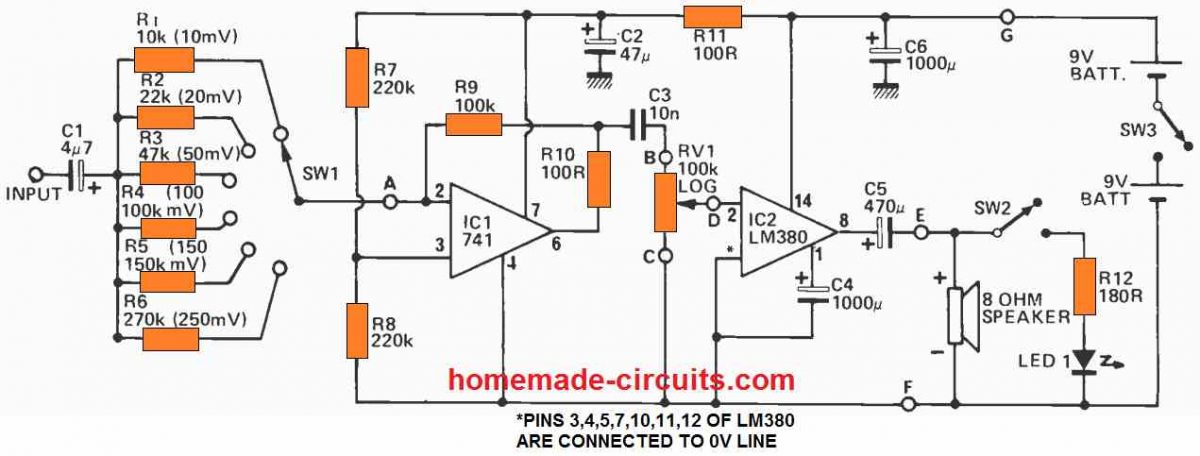
In order to determine an A.C. signal, you have to rotate the volume control to the highest level, and connect the input signal to the socket and start with the switch SW1 positioned to select the minimum sensitivity, until LED just lights up. The input signal value can be now determined by the position of the switch.
The gain of 1C1 which is a 741 op amp, is fixed through the ratio of the resistive divider formed by R9 and R1 to R6. The resistors R1 to R6 adjust the 741 gain from a level of 20 to 0.5.
Hence, in order to generate 100mV across RV1, the amount of input signal would be around 5mV to 200mV. Resistors R7 and R8 does the work of biasing the non-inverting input to 4.5V, while the resistor R10 is incorporated to safeguard the IC.
Considering that D.C. gain of this bench amplifier circuit has the value of unity, the output could be established with +4.5V D.C., enabling highest voltage swing functionality.
In order to decrease the output offset, resulting from the bias current, the value of the parallel resistor R7 and R8 must be roughly identical to the value of the R9. Remember the above point, if you wish you use a different supply voltage for this bench amplifier circuit.
Resistor R11 and capacitor C2 do the work of decoupling the 741 supply lines, just like the capacitor C6 does for the IC LM380. It may be possible to increase the value of capacitor C6 for getting a better DC, if the supply voltage is not regulated and stable.
PCB Design
The complete PCB track layout for the above explained bench amplifier is given below:

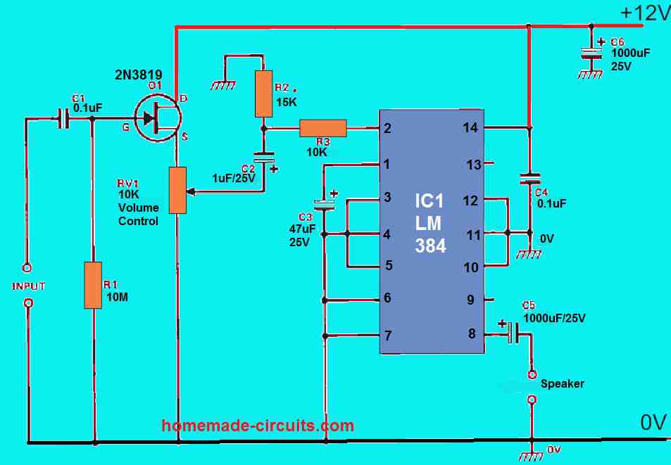
Parts List
Another Simple Design
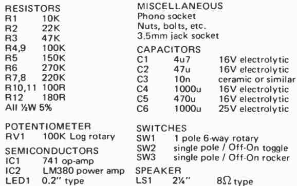
The next simple bench amplifier was created with a cheap cost and high functionality in consideration. A couple of panel-mounted terminal connections provide access to the unit's high-impedance (10 M) input stage. The unit is powered by a 12V DC mains adapter and has a 4 W output into an 8 Ohm speaker.
External speakers can be linked to the device through a second set of panel-mounted terminal connections, that are meant to be used with the bench amplifier.
The amplifier performs most efficiently with external 8 Ohm speakers, although it may be used with whatever speaker impedance from 4 Ohm to 16 Ohm. Distortion is generally lower than 0.1 percent at 1 W at 1 kHz, indicating acceptable fidelity. At 200 kHz, the frequency response is nearly flat.
Because the circuit is so simple, there isn't much we may say about it. Q1 is a unity-gain buffer amplifier with a high-impedance FET (field effect transistor). RV1, the volume control, feeds its output to IC1's input. IC1 is a 5 W power amplifier (really a higher-power equivalent of the LM380 2 W IC) with an integrated heat sink connected to the three center pins on either side of the IC package.
The power amplifier's output is routed by C5 to an external speaker, and the entire setup is supplied by a 12V AC to Dc adapter.
The IC's output is short circuit proof, as per the producers, and may be used with speakers with impedances ranging from 4 Ohm to 16 Ohm. The circuit works well with 8 ohm speakers in reality. Our IC is connected to a PCB heat sink and has an extended surfaces clip-on heat sink to guarantee proper power handling capacity.


Comments
Sir I have an amplifier Now I want to add several (3-4) input for this amplifier.. what can I do ?
Hi Farhan, you can add the following circuit to your amp input:
https://www.homemade-circuits.com/wp-content/uploads/2021/05/single-transistor-mixer-circuit-compressed.jpg