In this article I have explained a battery status indicator circuit which can be also used as a battery charging fault indicator circuit. The idea was requested by Mr. Faizan.
The Design
The idea presented here takes care of all the parameters required for charging a battery ideally and safely.
Referring to the shown battery charging fault indicator circuit, the design may be understood with the help of the following points:
The IC LM3915 which is a dot/bar LED display driver IC forms the main charging indicator module of the circuit.It's pin5 is the sensing input, the rising battery voltage is sensed at this pin and the IC responds to it by producing a proportionately sequencing LED illumination across its 10 outputs, as shown with the 10 connected LEDs.
A LM317 IC can also be seen attached at the input of the circuit, it's wired as a constant current generator so that the circuit is able to produce error free indications and operations regardless of the input current level. Rx is selected suitably in order to enable this correctly.
Circuit Diagram
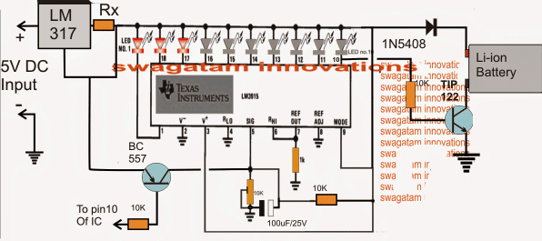
When power is switched ON, the 100uF/25V capacitor across the pin5 preset of the IC momentarily grounds pin5 so that all the outputs of the IC begin by staying shut off.
This is important to make sure that the TIP122 is able to initiate the charging process and the BC557 is inhibited from an accidental switch ON due to the initial surge transients.
As soon as the 100uF is charged up, pin5 is allowed to sense the actual voltage that's been utilized by the battery while it's been charged, which should be normally anywhere around 3 to 3.3V for a fully discharged 3.7V Li-ion battery.
Here each LED may be set to indicate an increment of 0.42V, which implies that the illumination of the 10th LED indicates 4.2V which may be assumed to be the battery full charge level indication.
This also implies that during power ON, 7 LEDs must be illuminated to indicate a correct battery discharge level and charging process.
Less that 7 LEDs illuminated would indicate a badly discharged battery or a damaged battery consuming excess current than the specified range.
With all the LEDs lighting up during power switch ON would imply either the battery is fully charged or the battery is not accepting charge and is faulty.
Under normal conditions, around 7/8 LEDs should be illuminated at power switch ON and as the battery voltage increases due to charging, the LEDs should also sequence by illuminating the 8th, 9th and the 10th LED sequentially.
Once the 10th LED is illuminated, a low logic is sent to the base of the TIP122 which is now inhibited from a base bias and the charging voltage to the battery is thus cut off, switching off the charging voltage to the battery.
The low logic from the 10th pin is also sent to the base of the shown BC557 which conducts and connects pin5 of the IC directly to the 5V supply making sure that the 10th LED becomes latched and the situation is locked until power is switched OFF and ON for further actions.
How to the set up the circuit
It's the simplest part in the design.
Initially do no connect any battery across the shown points.
Apply a precise 4.2V at the input.
Now begin adjusting the pin5 preset such that the LEDs light up sequentially and the 10th LED just illuminates brightly.
Seal the peset once this is confirmed.
Your battery charging fault indicator circuit is all set now for the proposed battery fault indications and also charge level indications.
Battery Fault indicator Circuit using a Flashing LED.
The following update shows a simpler design that may be used for indicating a battery charging malfunction through a flashing LED
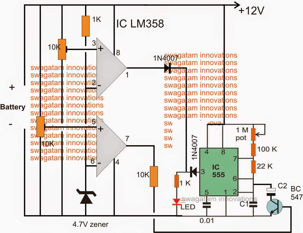
Initially both the opamp outputs may be assumed to be low, if the battery is discharged below 11V, this will be indicated with a fast blinking of the LED. C1 must be set for achieving this fast blinking.
The lower opamps is set using pin5 preset such that when the connected 12V battery reaches around 12.5V, its output pin goes high, once this happens the BC547 triggers and adds a high value capacitor C2 in parallel with C1 slowing down the flashing rate significantly and indicating that the battery has entered the next upper charging phase and also that the battery is good and is accepting the charge well.
As the battery continues to get charged and acquires a voltage level of around 14V, the upper opamp which is set using pin3 preset to trigger at this point triggers and renders a high across the connected LED stopping its flashing and illuminating it to solid.
Once this happens the user may assume the battery to have reached the optimal charging level and may remove it from the charger.
How the Battery fault is Indicated
1) If the LED blink rapidly would initially indicate that the connected battery is over discharged, however this condition should improve and the LED should transit into a slow flashing after an hour or so depending upon the sate of the battery. If this does not happen, the battery may be assumed not accepting the charge due to internal damage or short circuit.
2) If the LED lights up solid when power is switched ON would clearly indicate a faulty battery which may be completely inactive internally and unable to accept any current.
The above explained battery charging fault indicator circuit can be upgraded for an automatic over charge cut off through some modification as shown in the following diagram:
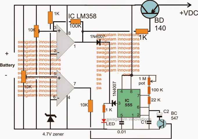
While setting up the two presets make sure the 100K link remains disconnected in the upper opamp.
After setting up the thresholds, the 100k link can be reconnected into position.
The circuit will not initiate until a battery is connected, so make sure the battery to be charged is first connected and then power is switched ON.
For a 3.7V battery, the 4.7V zener must be replaced with two
A little in-depth investigation shows that in the above circuit C2 will not have a discharge path through the connected BC547 and therefore it won't help to slow down the oscillations while the lower opamp is in the activated state.
The correct implementation of the above concept could probably be done by using an optocoupler as shown in the following figure.
Here instead of targeting the frequency determining capacitor C2 the resistor counterpart is selected for the intended control of the frequency and LED blinking rate:
Schematic for Blinking LED Fault Indicator
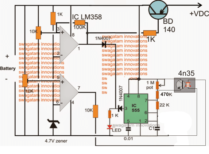
Now it looks much better.


Questions & Answers
Thanks for circuit.I want to know about Rx value i have selected it 2ohm 5watt for 0.6A charging current is it OK?
Also tell me about BC557 transistor which is PNP not NPN should it be 547? or 577?.
I am using switching power supply of 5v,3A is it OK to use ?
Rx = 1.25/charging current,
for a 1000mAh Li-ion batt the charging current should be 1amp, therefore
Rx can be = 1.25 ohms
BC557 is PNP
5V/3amp input is OK
Can i use LM3914 in place of LM3915?
yes 3914 will do.
By mistake i put the BC557 question i got it,it is PNP.
Can it tell the short circuiting of battery or reverse polarity as well?
battery cannot get short circuited in the above design.
for reverse indication polarity simply add a LED with a 1k series resistor across the emitter and ground of TIP122 but in reverse polarity that is anode to ground and cathode to the emitter.
One more question about setting up LM3914 does the input 4.2V means by providing input at pin 9 by removing the LM317 to tune it up?
input should be applied across the points where 5V is indicated, that is at the input of LM317, it should not be removed.
once the IC is set, then the 4.2V can be removed and replaced with 5v
Hello;
As the LM317 drops 1.25volts so the output is less then we need to charge up the battery so what should be done in order to get correct output at TIP122?
Are you sure the 317 will drop 1.25V? If it is so, then you may have to use a 6V input instead of the shown 5V
Very strange behavior from circuit when only +ve terminal of battery connected to the TIP122 all of bar graph ON as battery is not connected to GND and not fully charge this happens every time and no current charging current is sensed.My battery is OK i have test with another charger.
connect a diode in between the battery positive and the TIP122 emitter, this will solve the issue.
anode to emitter, cathode to the battery positive.
this is not working as the output across TIp122 is below 2v which is low when input is 5V.
change the position of the battery as shown in the updated diagram…
For status LED i need to have some changes like:
1:Green LED fast flashing indicates fault
2:Green LED slow indicates charging condition
3:Green LED solid ON indicates battery is full charge.
in the above design it would be difficult to add these enhancements, if possible i'll try to design a new circuit.
Sure i will wait for this.Thanks
Any updates?
I tried but couldn't figure out a proper design till now…
https://www.homemade-circuits.com/2013/12/usb-automatic-li-ion-battery-charger.html can this be modified?
the above design is based on a different principle so it cannot create flashing indications,
for flashing indication a different circuit will be required having the caapcbility to sense the battery condition and change the flashing rate.
Yes surely it needs a new one
Any updates i am waiting anxiously?
I have the idea, but unable to update it due to the lack of time….will do it soon for sure.
OK i am waiting because i have to do in this week.Thanks,
fast flashing for fault,
slow flashing for charging
and very slow flashing may be at 1 flash per 2 seconds
this much can be provided.
For status LED i need to have some changes like:
1:Green LED fast flashing indicates fault i-e 1 flash per 2 seconds agreed.
2:Green LED slow indicates charging condition agreed.
3:Green LED solid ON indicates battery is full charge please check.
sorry it's not working out.
with 4 static LEDs it may be possible but not with a single flashing LED
Oh that's sad.Please let me know other options? if not working with LM3914.
First of all a proper charger needed with cut-off,secondly a multivariate can be connected to have charging status?.For fault indication that is tricky to have fast flash may be with 555 timer?
introducing two 555 stages for just flashing an LED could make the design so much lengthy and bulky,
using 4 separate solid LEDs makes more sense according to me. which will light up individually (not together) for indicating the various conditions of the battery
Solid need for charge completion only.
i'll try to do it, but the circuit will be quite lengthy and bulky.
you'll get it tomorrow
Can the flashing can be done with 2 transistor multivibrator?
yes, and the following can also be used
https://www.homemade-circuits.com/2011/12/how-to-make-single-transistor-led.html
so that means the circuit can be little smaller.I will wait for the whole circuit diagram.Thanks.
OK!
still working on it, possibly I'll finish it by tomorrow
diagram updated check it out
SO how this can be used for charging a lithium ion battery?.
What is the value of C1,C2?
Does it will work for slow flashing and for fast flashing?
yes it will work as per your mentioned specifications
for a li-Ion feed a 4.2V input, adjust the 10k preset such that at 3.5V, the lower opamp output just switches ON (become high).
Use a 7555 instead of 555 because 555 may not work below 4.5V
C1 = 1uF, C2 = 2.2uF
OK what will be the input voltage in this case?
it'll be 4.2V
any change in value of zener?.
C1=1uf multilayer or ceramic ?
C1, C2 both can be electrolytic
What will be the value of zener for 4.2Volt case?
you can two 1N4007 diodes in series with cathode to ground.
OK what circuit is best suitable for charging lithium ion battery 4.2v,1200mah? with cut-off,over charging protection.In this case the battery is attached to a charging circuit?.