For a novice, to understand more on Free Energy Receiver concept, let’s consider a solar-electric panel; widely used as an alternative to electrical energy.
Discussing Nikola Tesla's Free Energy Concepts
The invention of Nikola Tesla differs, but the closest thing to his invention can be found in a conventional energy - the photo-voltaics.
One major difference with the conventional solar-electric panel; it consists of a substrate coated with crystalline silicon, which is substituted with amorphous silicon now-a-days.
The conventional solar-panels are pricey and are still manufactured by following the conventional disciplinary process.
Solar Panel by Tesla
However the solar-panel developed by Nikolas Tesla is nothing but a dazzling metal plate with a transparent coating of any insulated material, which today is nothing but a spray plastic.
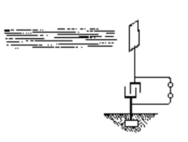
Hang up the antenna-like panels on a higher end, and use wiring to one side of a capacitor, while the other end fixed firmly to the earth; the capacitor will start receiving energy directly from the Sun.
In order to discharge the capacitor in a rhythmic level; connect across the capacitor with a switch, thereby producing electrical output.
The patent of Tesla indicates that it is very simple to derive electrical energy. The more the insulated plate is bigger, the more the generation of current.
This concept differs from ‘solar-panel’, since it doesn’t need sun-rays for operation. It can even work perfectly at night.
However the connoisseurs of science refute the idea, considering it to be unachievable. And this is one reason for not getting a patent on such kind of invention.
Later, many scientists have defined the same in a much more complicated way. Nikolas Tesla, during his invention faced severe problem with the patent committee; who had examined his work. But the inventor of today’s free-energy gets it tougher.
During the time of Tesla, the U.S Patent Office was chaired by an appointee of Reagan, whose experience in the past was a hi-level executive with Philips Petroleum.
Free Energy Patent for Tesla's Invention
Tesla's free-energy receiver was patented in 1901 as “An Apparatus for the Utilization of Radiant Energy.”
The patent refers to "the Sun, as well as other sources of radiant energy, like cosmic rays." That the device works at night is explained in terms of the night-time availability of cosmic rays. Tesla also refers to the ground as "a vast reservoir of negative electricity."
Tesla’s invention of free-energy receiver first got its patent in the year 1901, defining it to be as an apparatus for the Utilization of Radiant Energy.
The patent clearly refers to “the Sun, as well as other sources of radiant energy, like cosmic rays.” Its capability to work in the night is explained further with the energy available from cosmic rays. He even stated the earth ground as “a vast reservoir of negative energy”.
The presence of radiant energy and the possibility to generate free-energy is what Tesla’s inspiration. He referred the Crooke’s Radiometer as “A Beautiful Invention”.
Tesla’s thought was to generate energy directly from mother-nature. His free-energy receiver was the closest invention at per with this thought.
However on his 76th Birthday, while calling up a press conference despite his insolvency, announced the idea of a “cosmic-ray motor”.
He even mentioned the power of “cosmic-ray motor” is thousand times powerful than the “Crooke’s radiometer”.
How the Circuit works
The potentiality to generate electricity between the elevated plate (plus) and the ground (minus), the energy stars generating in a capacitor, and after a permissible time interval, the energy accumulated, manifest a powerful discharge.
However in order to make this happen and according to Tesla, the capacitor should have the power to amount higher electrostatic capacity, while the dielectric should be made from the best available quality of Mica. Without this, it may destroy a dielectric.
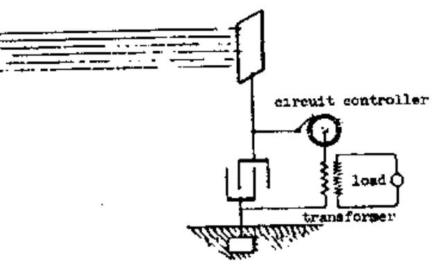
Nikolas Tesla proposed various options for the switching device. One of them is a rotatory switch similar to a Tesla circuit controller.
Another is the electrostatic device, which consists of two light and thin conductors suspending in the vacuum.
This starts gathering up energy in the capacitor, as one positive and others negative. Upon a certain level of charge, they are attracted and touch each other to generate fire in the capacitor.
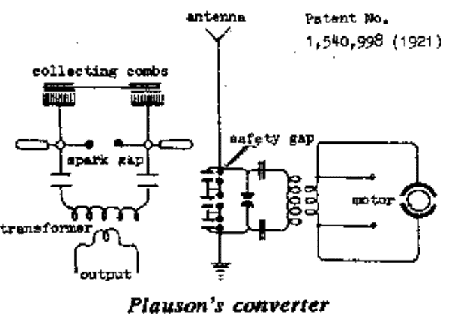
Another type of switch mentioned by Tesla consists of a minute air gap or weak dielectric film which gets immediately broken upon achieving certain potential.
The aforesaid procedure and the technicalities are defined in the patent of Tesla. However going through the patent and further studies in this regard, I came across few references in-line with Tesla’s invention.
But that’s just gathering of theoretical knowledge as I haven’t experimented further on them.
Submitted By: Dhrubajyoti Biswas


Questions & Answers
Hello Mr Swagatam.
i see you are interested in the unconventional’ energy source.
Ions Power Group in Florida does the same with its antennas and charges Grafenne batteries .
Their experimental model does not include a plate or even several strands of’antennes which, I think reduces the efficiency of the’funnel.No high-voltage transformer type Tesla coil either .
Their video is to be seen on the internet.
In another area, an interesting montage is that of William Skinner’s Gravity Power in 1939 .
the model presented is 4 elements but there is a 1 element assembly easier to understand and manufacture.
that is, if this information can be useful. Good discoveries.
Nikola Tesla’s Wardencliffe Tower with its unfinished copper foil dome is the typical capacitive antenna.
It functions like a capacitor plate with the earth and the ionosphere, and serves as a funnel to collect electrical energy, which charges the capacitor in the grounded design.
When the capacitor reaches a certain voltage, the current discharges through the vibrating switch, which can be a small neon bulb in a relatively low-voltage circuit of about 100 volts, or a spark gap, as seen in Hermann Plauson’s designs, which use an air-filled transformer without a metal core, like a high-voltage Tesla coil.
An old, insulated short-wave radio tower could be used for experimenting with these circuits; as they are inaccessible to most of us, an electric animal fence wire pulled by a kite far from power lines on a cloudless day is also suitable. There is also a circuit made up of a Rhumkorf coil or automotive ignition coil that we see on Pinterest.
Thanks for the interesting information…
There is a phenomenal amount of’ electrical energy between the earth and the ionosphere, and’ is what charges clouds with electricity by electrostatic influence.
the present diagram is that of’a condenser antenna isolated from the ground which can have the shape of the dome of the wardenclife tower of Nikola Tesla, d’a balloon covered with fabric of’aluminium like Hermann Plauson,d’a satellite antenna returns to the’ upside like a plate at the top of’an isolated pylon, aor’an electric fence wire towed by a kite away from power lines and on a cloudless day.
Replace the Switch vibrating with a small Neon tube and take a 230 /12 volt transformer and a 400 volt capacitor between the’ antenna and the ground .
Contact your local radio club.
Thanks for the interesting information, appreciate it very much…
Mr. swagatam Nikola Tesla was a great scientist of all time. The free energy concept is a subject to ponder upon. Here the dimensions of the plate is not given that remains unclear. I would myself like to try the experiment.
Moreover about ten to twelve years ago I conceptualized a similar device to get electricity from charged air with two metal foils having a minimum gap. But couldn’t give effect to it due to preoccupation in my professional work. A couple of years before I have come to know about the air battery which is similar to my concept. Hope to get more light in future. Thank You
Thanks Robin, for the useful feedback, appreciate it. Please keep up the good work!
Hello. That those crystals used to barely tighten our headphones and today, in connection with free energy, they are used behind the antenna of the MV diode and are driven by motors. Sir, I don’t understand. Thanks for the reply and best regards. Your admirer, how much time you spend for the electrical engineering public.
Thank you Marian, the article was submitted by an external author, so I have not yet gone through it…anyway appreciate your feedback.
Great website indeed. When Tesla tested his Battery-less engine-less car..it was made of an electric drive motor powered by a circuit that collects energy though an antenna. It is said to reach 90 miles/Hr in speed. This may not be similar to the above circuit simply because car cannot have earthing while it moves…except maybe it own chasis..This car alarmed oil & combustion industry which was about to take off at that particular era..Tesla made it worse when he informed Morgan that he was planning to enter Morgans office thru window using a flying vehicle that also runs on free energy. How unlucky humans on this planet? that era steered humanity into an endless economic & energy slavery…with years, energy tycoons accumulated wealth & power, so huge to suppress hundreds of other free energy inventions to come. It turned out that tapping into free energy has many doors & methods..Will slaves on this planet ever make it to freedom?..in fact it is a big hard-labor prison.
I don't want to sound critical, because we think Tesla's concepts are sound, but I don't see how Ronald Reagan appointed a chairman to the US patent office during the time of Tesla. Nikola Tesla passed away in 1943, and Reagan didn't even become Governor of California until 1967. Reagan's presidency began in 1984, 41 years after Nikola Tesla's death.
I'm not nit-picking, but so much disinformation already exists about Tesla, that any presentation of his ideas would have far more credibility with the historical record intact. That said, you still have our sincere gratitude for your work, and what you're doing to get these ideas into the public domain. Thank you, and I look forward to testing these circuits and publishing results for the benefit of all.
I think the writer of the above article misinterpreted the lines…the original write up was probably written and published at the time when Reagan was in power and its author meant to say that it was even tougher during then to get patents for such inventions.
Anyway, Thank you for providing your precious thoughts on the subject, I truly appreciate it a lot.
hi mr. swagtam please send to me the detail explanation of the how to collect free energy from atmosphere
hi adugnaw it's already been given in the related posts of this blog, you may refer to them.