• Skip to main content
  • Skip to primary sidebar

Homemade Circuit Projects

Need circuit help? Post them in the comments! I've answered over 50,000!

Blog | Categories | About | Contact | Calculators-online
You are here: Home / Sensors and Detectors / Clap Operated Toy Car Circuit

Clap Operated Toy Car Circuit

Last Updated on July 25, 2019 by Swagatam 9 Comments

In this post we study how to make a simple clap operated toy car circuit using a clap switch circuit and a MIC amplifier, to control its forward and reverse movements,  in response to the claps of the user. The idea was requested by Mr, Zeeshan.

Table of Contents
  • The Design

This clap operated toy car is will move in forward or reverse directions every time a clap sound is generated.

Circuit Objectives and Requirements

  1. I urgently need a circuit diagram. I need a circuit of a toy car which goes forward and reverse on the sound of clap.
  2. After switching on, car goes forward ( motor rotate clockwise).
  3. After a clap sound car goes reverse( motor rotate anti clock wise). and vise versa.
  4. In other words, toy motor change it's rotation from clockwise to anti clockwise and vise versa by clap sound. If possible make it using 3 or less pencil aaa cells.
  5. If yes please help me by providing me so.

The Design

The above requested idea of a clap operated toy car circuit can be implemented using the following simple circuit:

Clap Operated Toy Car Circuit

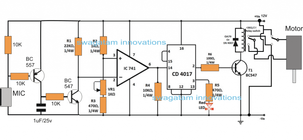
The circuit is made up three basic stages: the MIC amplifier stage, the opamp comparator stage and an IC 4017 based flip flop stage.

The IC 741 is configured as a comparator and together with the IC 4017 it forms a basic clap operated switch circuit.

The BC557/BC547 constitutes the MIC amplifier circuit, we have used two transistors here to make the design highly sensitive to the clap sounds.

Whenever a clap sound or any similar sound is detected by the MIC, it instantly conducts and causes a low signal across its leads enabling the BC557 to trigger.

BC557 triggering forces the BC547 to conduct even harder and in the course brings the pin#2 of IC 741 to ground level or lower than the pin#3 reference pin of the IC. This action enables the opamp output to go high causing a positive trigger for the 4017 input pin#14.

The above functioning forces the IC 4017 to change states across its output pins #2 and pin#3 alternately with every clap sound detection.

The output from the IC 4017 can be seen connected with a relay driver stage consisting of a DPDT relay with its dual contacts configured with the toy car motors, and the supply rails.

The flip flop action from the IC 4017 output toggles the relay contacts across their N/C and N/O points, thereby causing the car motor to correspondingly rotate in cock-wise and anticlockwise directions in response to the subsequent clap sounds, and thus the car is able to move forward or backward accordingly.

In order to make this clap operated toy circuit make sure to wire the indicated relay contacts across both the motors of the car which may be attached at the front of the rear sides of the unit, and must have a gear box configured with the wheels.

You'll also like:

  • 1.  2 Simple RF Detector Circuits Explored
  • 2.  Motion Detector Circuit using Doppler Effect
  • 3.  Home Electromagnetic Radiation Detector Circuit
  • 4.  INA219 Current Sensor Circuit Diagram and Datasheet
  • 5.  5 Simple Motion Detector Circuits using PIR
  • 6.  Make this Simple Weather Station Project for Homes and Offices

About Swagatam

I am an electronics engineer with over 15 years of hands-on experience. I am passionate about inventing, designing electronic circuits and PCBs, and helping hobbyists bring their projects to life. That is why I founded homemade-circuits.com, a website where I share innovative circuit ideas and tutorials. Have a circuit related question? Leave a comment.... I guarantee a reply!

Previous Post: « Make this Simple Weather Station Project for Homes and Offices
Next Post: High Current Wireless Battery Charger Circuit »

Reader Interactions

Comments

  1. Virendra parihar says

    September 19, 2020 at 2:12 pm

    Sir. I m going to make this circuit but I have some confession to take this circuit diagram. I can’t be understanding Relay connections. How many and which types relays r being used here. Relay code ?

    Reply
    • Swagatam says

      September 20, 2020 at 2:11 pm

      Virendra, the relay is a DPDT relay which stands for double pole double throw, and has two sets of identical contacts which operate together.

      Reply
  2. Shiva Kumar B says

    March 15, 2018 at 7:00 am

    Sir , in place of BC 557 transistor can we use BC547
    & What’s main difference bw them

    Reply
    • Swagatam says

      March 15, 2018 at 8:57 am

      Shiva, you can try it, make sure to connect the emitter towards the base of the other BC547

      Reply
  3. Tapan Patil says

    January 29, 2017 at 1:46 pm

    hellow sir i want to make a home automation system as my last year project please refer me one and your website is fandastic one

    Reply
    • Swagatam says

      January 30, 2017 at 3:41 am

      Thank you tapan, presently I do not have a full-fledged home automation circuit, possibly I'll try to present one soon,

      Reply
  4. rupet the genius says

    January 26, 2017 at 2:32 pm

    4017 is wrong! it should e a 4013 type flip/flop

    Reply
  5. dean says

    January 24, 2017 at 9:04 pm

    Swagatam – I'm looking for a timer circuit. The type that is used in electronic candles (and christmas decorations) to turn them on 4-5 hours and then off 20-19 hours. Then repeat that on/off cycle everyday. Those electronic candle circuits are small, about the size of a US dime, and can handle 3 to 6VDC. Am not asking you to design one – if you have a similar one in your list…just point me towards it. Love your web site !!

    Reply
    • Swagatam says

      January 25, 2017 at 3:04 am

      thanks dean, I think you can try the following concept, you can use SMD parts to make it really compact:

      https://www.homemade-circuits.com/2012/04/how-to-make-simple-programmable-timer.html

      Reply

Need Help? Please Leave a Comment! We value your input—Kindly keep it relevant to the above topic! Cancel reply

Your email address will not be published. Required fields are marked *

Primary Sidebar

Subscribe to New Circuit Ideas

Categories

  • Arduino Projects (87)
  • Audio and Amplifier Projects (132)
  • Automation Projects (17)
  • Automobile Electronics (101)
  • Battery Charger Circuits (83)
  • Datasheets and Components (104)
  • Electronics Theory (143)
  • Free Energy (37)
  • Games and Sports Projects (11)
  • Grid and 3-Phase (19)
  • Health related Projects (25)
  • Home Electrical Circuits (12)
  • Indicator Circuits (14)
  • Inverter Circuits (87)
  • Lamps and Lights (142)
  • Meters and Testers (69)
  • Mini Projects (46)
  • Motor Controller (64)
  • Oscillator Circuits (27)
  • Pets and Pests (15)
  • Power Supply Circuits (108)
  • Remote Control Circuits (50)
  • Security and Alarm (64)
  • Sensors and Detectors (101)
  • Solar Controller Circuits (59)
  • Temperature Controllers (42)
  • Timer and Delay Relay (49)
  • Transmitter Circuits (29)
  • Voltage Control and Protection (37)
  • Water Controller (36)

Calculators

  • Battery Back up Time Calculator
  • Capacitance Reactance Calculator
  • IC 555 Astable Calculator
  • IC 555 Monostable Calculator
  • Inductance Calculator
  • LC Resonance Calculator
  • LM317, LM338, LM396 Calculator
  • Ohm’s Law Calculator
  • Phase Angle Phase Shift Calculator
  • Power Factor (PF) Calculator
  • Reactance Calculator
  • Transistor Astable Calculator
  • Transistor base Resistor Calculator
  • Voltage Divider Calculator
  • Wire Current Calculator
  • Zener Diode Calculator
  • Filter Capacitor Calculator
  • Buck Converter Calculator
  • Boost Converter Calculator
  • Solar Panel, Inverter, Battery Calculator
  • Wire Current Calculator
  • SMPS Transformer Calculator
  • IC SG3525, SG3524 Calculator
  • Inverter LC Filter Calculator

People Also Search

555 Circuits | 741 Circuits | LM324 Circuits | LM338 Circuits | 4017 Circuits | Ultrasonic Projects | SMPS Projects | Christmas Projects | MOSFETs | Radio Circuits | Laser Circuits | PIR Projects |

Recent Comments

  • Swagatam on Battery Deep Discharge Protection Circuit
  • Swagatam on 10 LED Tachometer Circuit Diagram
  • Drew Adare on How to Collect Free Energy from Atmosphere
  • Göran on 10 LED Tachometer Circuit Diagram
  • Abdulmajid Haruna on Laptop Power Bank Circuit

Company

  • Privacy Policy
  • Cookie Policy
  • About Me
  • Contact
  • Disclaimer
  • Copyright
  • Videos
  • Sitemap

Social Profiles

  • Twitter
  • YouTube
  • Instagram
  • Pinterest
  • My Facebook-Page
  • Quora
  • Stack Exchange
  • Linkedin
  • © 2025 · Swagatam Innovations