• Skip to main content
  • Skip to primary sidebar

Homemade Circuit Projects

Need circuit help? Post them in the comments! I've answered over 50,000!

Blog | Categories | About | Contact | Calculators-online
You are here: Home / Lamps and Lights / Flashlight Circuit with Long Backup and High Efficiency

Flashlight Circuit with Long Backup and High Efficiency

Last Updated on July 24, 2024 by Swagatam 2 Comments

There are two main advantages of this highly efficient flashlight circuit with long backup. Firstly, it uses only a single 1.5V AAA cell and illuminates a 3.3V LED. Secondly, the 1.5V cell is consumed by the LED until there's virtually no charge left in it.

Table of Contents
  • Circuit Description
  • Parts List

Due to these features, this flashlight is able to last many months without the need of frequent replacement of the battery. This ultimately saves money and time for the user.

So, how does this flashlight keeps the LED illuminated until the last drop of charge is used up from the battery?

You guessed it right. This flashlight design incorporates the famous joule thief circuit which enables it to become so efficient.

Circuit Description

warning message: electricity is dangerous, proceed with caution
simple joule thief circuit

If you do not want to read the whole explanation below, you can watch the video instead:

The working of the circuit can be understood with the following points:

This joule thief circuit is actually a blocking type oscillator, also referred to as vampire torch.

When the 1.5V is switched ON, the voltage passes to the base of the T1 BC547 transistor via the R1 1k resistor and the left side winding of TR1.

This switches ON the transistor T1 instantaneously causing the the right side winding to be grounded by the collector/emitter of T1.

Due to this, the full 1.5V now instantaneously gets diverted to ground via the right side winding of TR1 and the T1 collector emitter pins.

In this situation the voltage to the T1 base is momentarily inhibited, causing T1 to turn off instantaneously.

As soon as T1 is turned OFF, the voltage to the right side winding is cut off, causing a boosted flyback voltage to kick-in across the LED.

This instantaneous boosted voltage illuminates the LED brightly.

However, now, the T1 base is yet again able to get the biasing voltage via R1 and the left side winding. T1 is now switched ON, and the ON/OFF cycle simply keeps repeating.

This causes the circuit to oscillate rapidly at a high frequency.

The above high frequency switching of T1 and the TR1 causes the LED to remain constantly illuminated through the boosted voltage frequency from the right side winding.

Due to persistence of vision, the LED appears to be illuminated constantly with high brightness.

The circuit continues to work and keep the LED illuminated until the battery voltage reaches below 0.3V, or until there's hardly any charge left in the 1.5V cell.

Without the above joule thief circuit a 3.3V LED would never illuminate through a 1.5V cell.

If a 3V source is employed using two 1.5V series cells, the LED would illuminate but only until the battery is discharged to 2V. Meaning each cell would still have around 1V left in them, which is then wasted inside the battery.

The above situation is avoided in this circuit, allowing the flashlight LED to work with only a single 1.5V AAA cell and remain illuminated until the cell is completely exhausted.

Because of the features, the proposed LED flashlight becomes 5 times more efficient, long lasting, and extremely economical.

To further enhance the illumination brightness, the LED could be positioned inside a polished reflector base.

Parts List

  • Resistor 1k 1/4 watt CFR = 1
  • Transistor BC547 or 2N2222 = 1
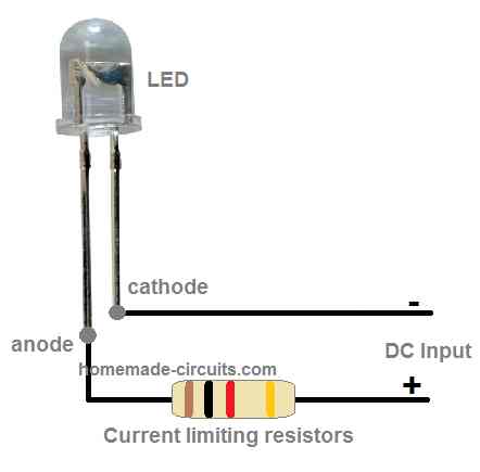
  • LED 3.3V straw hat type = 1
  • Transformer using Ferrite ring = 1
  • 1.5V AAA Cell = 1

You'll also like:

  • 1.  Simple Hi Efficiency LED Torch Circuit
  • 2.  Transformerless Current-Controlled LED Bulb Circuits you can Build at Home
  • 3.  Arduino RGB Flowing Sequential Light Circuit
  • 4.  CREE XM-L T6 LED Driver Circuit – Specifications and Practical Application
  • 5.  Converting Ordinary Rice Bulb String Light to LED String Light
  • 6.  How Crank Flashlights Work

About Swagatam

I am an electronics engineer with over 15 years of hands-on experience. I am passionate about inventing, designing electronic circuits and PCBs, and helping hobbyists bring their projects to life. That is why I founded homemade-circuits.com, a website where I share innovative circuit ideas and tutorials. Have a circuit related question? Leave a comment.... I guarantee a reply!

Previous Post: « Car Battery Warmer Circuit
Next Post: LM35 IC Temperature Controller Circuit with Push Button »

Reader Interactions

Comments

  1. Anto Das8 says

    November 10, 2024 at 8:23 pm

    Is TR1 a transformer and if it is, what is the voltage and current rating

    Reply
    • Swagatam says

      November 11, 2024 at 8:06 am

      The details are given in the diagram…

      Reply

Need Help? Please Leave a Comment! We value your input—Kindly keep it relevant to the above topic! Cancel reply

Your email address will not be published. Required fields are marked *

Primary Sidebar

Subscribe to our newsletter!

Categories

  • Arduino Projects (87)
  • Audio and Amplifier Projects (132)
  • Automation Projects (17)
  • Automobile Electronics (101)
  • Battery Charger Circuits (83)
  • Datasheets and Components (104)
  • Electronics Theory (143)
  • Free Energy (37)
  • Games and Sports Projects (11)
  • Grid and 3-Phase (19)
  • Health related Projects (25)
  • Home Electrical Circuits (12)
  • Indicator Circuits (14)
  • Inverter Circuits (87)
  • Lamps and Lights (142)
  • Meters and Testers (69)
  • Mini Projects (46)
  • Motor Controller (64)
  • Oscillator Circuits (27)
  • Pets and Pests (15)
  • Power Supply Circuits (108)
  • Remote Control Circuits (50)
  • Security and Alarm (64)
  • Sensors and Detectors (101)
  • Solar Controller Circuits (59)
  • Temperature Controllers (42)
  • Timer and Delay Relay (49)
  • Transmitter Circuits (29)
  • Voltage Control and Protection (37)
  • Water Controller (36)

Calculators

  • Battery Back up Time Calculator
  • Capacitance Reactance Calculator
  • IC 555 Astable Calculator
  • IC 555 Monostable Calculator
  • Inductance Calculator
  • LC Resonance Calculator
  • LM317, LM338, LM396 Calculator
  • Ohm’s Law Calculator
  • Phase Angle Phase Shift Calculator
  • Power Factor (PF) Calculator
  • Reactance Calculator
  • Transistor Astable Calculator
  • Transistor base Resistor Calculator
  • Voltage Divider Calculator
  • Wire Current Calculator
  • Zener Diode Calculator
  • Filter Capacitor Calculator
  • Buck Converter Calculator
  • Boost Converter Calculator
  • Solar Panel, Inverter, Battery Calculator
  • Wire Current Calculator
  • SMPS Transformer Calculator
  • IC SG3525, SG3524 Calculator
  • Inverter LC Filter Calculator

People Also Search

555 Circuits | 741 Circuits | LM324 Circuits | LM338 Circuits | 4017 Circuits | Ultrasonic Projects | SMPS Projects | Christmas Projects | MOSFETs | Radio Circuits | Laser Circuits | PIR Projects |

Recent Comments

  • Swagatam on 9 Simple Solar Battery Charger Circuits
  • Swagatam on Arduino Pure Sine Wave Inverter Circuit with Full Program Code
  • Swagatam on How Shunt Regulator TL431 Works, Datasheet, Application
  • Swagatam on Best 3 MPPT Solar Charge Controller Circuits for Efficient Battery Charging
  • Dan Biles on 9 Simple Solar Battery Charger Circuits

Company

  • Privacy Policy
  • Cookie Policy
  • About Me
  • Contact
  • Disclaimer
  • Copyright
  • Videos
  • Sitemap

Social Profiles

  • Twitter
  • YouTube
  • Instagram
  • Pinterest
  • My Facebook-Page
  • Quora
  • Stack Exchange
  • Linkedin
  • [genesis_subscribe_form]

    [genesis_subscribe_form]

    [genesis_subscribe_form]

    [genesis_subscribe_form]

    [genesis_subscribe_form]

    [genesis_subscribe_form]

    [genesis_subscribe_form]

    [genesis_subscribe_form]

    [genesis_subscribe_form]

    [genesis_subscribe_form]

    [genesis_subscribe_form]

    © 2025 · Swagatam Innovations