In this post I have explained how to convert smps into a solar charger circuit. The method will result in an extremely efficient and fast solar charging of the connected battery.
SMPS Solar Chargers
SMPSs have become very common nowadays and we find them being used in the form of AC to DC adapters wherever needed. The best example is our cell phone chargers which are actually compact SMPS 5V chargers.
Solar charger devices are also becoming popular nowadays and folks are constantly in look out for options in the form of solar chargers having the most efficient charging response.
Solar panels or PV devices are normally utilized for charging lead acid batteries which tends to take relatively long hours for getting fully charged, besides when the sunlight conditions are bad things start getting even more sluggish.
For tackling the above condition or rather for enabling quicker charging from solar panels, special MPPT based soar chargers have been developed which effectively monitor the solar panel maximum power point levels and generate the most efficient charging conditions for the connected battery.
In this article although we won't be discussing an ideal MPPT, yet the discussed method will give you an opportunity to acquire the most efficient way of charging your battery through a solar panel.
As proposed in one of my previous articles discussing understanding solar mppt solar chargers, a switch mode based power supply (SMPS) is probably the best option for making it work as a solar charger circuit, so here I have explained how to make an smps based solar charger circuit at home.
Making an SMPS can be quite complex and might require considerable amount of time and knowledge for the implementations, so here rather we will focus on how to convert a ready made smps into an effective solar charger circuit quickly.
For this you will require the following materials, assuming the battery to be charged is 12V rated:
A ready-made 120V or 220V to 12V SMPS unit having current rating equal to 1/5th of the battery AH which is to be charged.
A few Solar Panels whose total open circuit voltage equals around 100V.
Connecting wires.
Converting SMPS into a Solar Charger Circuit.
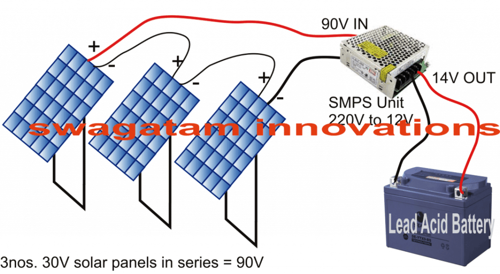
As we all know a normal mains SMPS are mostly rated with minimum of 85V to 100V input in order to provide the specified output DC, let's assume it to be 12V, meaning for acquiring 12V it must be supplied with a minimum of 100V at the input.
Keeping the above issue in mind, we must select a solar panel which may be able to produce approximately 100V for making the procured SMPS work.
Since PV panels with such high voltage might not be available, we may opt for many low voltage solar panels connected in series for generating the above voltage.
For instance you can go for 3nos. of 30V solar panels and connect them in series to get 90V from it, which might just do the job.
The above input supplied to the procured SMPS would generate the required 12V which may be directly attached to the battery for charging it efficiently.
However a 12V supply might not be enough to charge a 12V battery, we would need at least 14V for it, but that's not a big issue. You will find that most SMPS units have a small voltage adjustment preset situated just beside its connector, which can be appropriately adjusted to raise the 12V to 14V.
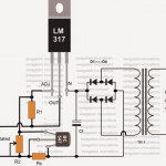
However, if you don't get an SMPS with this adjustment preset, you can very well open it and adjust the output voltage with some modifications. The procedures can be learned in this article which explains how to modify an SMPS circuit.
That's it, you have just now converted a ready made SMPS unit into an efficient solar charger circuit that might generate results equivalent to MPPT charger circuits for you.
Main Advantages
The key advantages of this SMPS concept is its compact configuration and a 90% efficiency enabling high current battery to get charged optimally and quickly.
For example we can use an SMPS rated to generate 20 amps, then we can charge a lead acid battery having an Ah rating of as high as 200 Ah, and if the battery is Li-Ion type then it can be as powerful as 40 Ah Li-ion battery.


Questions & Answers
Hello Sir,can the solar charger controller using smps work well with lithium ion batteries?
Geofrey
Hi Geoffrey, yes, you can effectively charge Li-ion batteries also using the above concept…
Hello Mr. Swagatam.
Is there a relatively basic circuit that simply controls a mechanical relay that switches off the current flow to the battery when it reaches full charge voltage? With this type of control I would only need to upgrade the capacity of the relay whenever I added additional panels to my solar bank. Thank you so much for your consideration of this idea.
Hello Paul, there are plenty of solar battery auto cut off designs available in this blog…from simplest to relatively complex ones.
The simple ones use transistors, while the complex ones use op-amps, please let me know which design would be preferable to you?
Hello Mr. Swagatam,
Thank you for sharing your knowledge.
I need to use ATX power supply with 700VDC input to step it down to 12VDC! what are the modifications required?
thanks again
Hello Osama,
Converting 700 V to 12 V efficiently looks hugely complex to me. Presently I do not have a proper SMPS circuit that would be able to do this.
Hello Mr. Swagatam,
Thank you for your answer, but the inverters that are allowed to be operated in Germany, mostly from SMA, will not come out in the event of a power failure, because they recognize the grid of the supplier and if the same shutdown fails. I then have 12 kWp on the roof, which I cannot use. Due to the different module cabling, there are module strings with 450 to 750 volts open circuit voltage. This should now be used in the event of a blackout in the German supply network in order to supply various battery banks consisting of one 24 V and three times 48 volts and their final charge voltage of 56 volts, mostly in the winter months with little radiation, in order to then use the heating pump and to supply the freezers, as well as to have some light. If there is also flooding, a pump would also have to be supplied. The 24 volt battery storage consists of lead with 600 Ah. The 48 volt memory made of Li cells at 6 kWh. There are 5 sine converters available that can provide the AC voltage of 230 volts from the 24 or 48/56 volts if the power grid should break down. The danger of such a breakdown is getting closer as most network operators invest too little in expanding the supply. In theory, it would be bad if you can’t even take care of yourself if this happens.
Kind regards, and a nice weekend to you,
Ronald
Hello Mr. Ronald, From the explanation I understand that basically you need a 600 V to 56 V inverter circuit. And the main ingredient required for building this inverter would be a 700-0-700V transformer with a secondary rating of 0-56V. If you could make this transformer accessible to you, rest can be easily implemented using any standard inverter topology.
Hello Mr. Swagatam
I came across your site by accident. I deal with similar things. The following problem and the best solution are sought. We have all connected many PV modules in series on the roof, there are voltages from 500 to almost 1000 volts, which are then fed into the grid via grid – controlled inverters. If there were a blackout in the supply, we would have no energy due to the network management, not even enough to charge a battery. But especially with such a blackout in winter, it would be good to be able to supply at least one battery bank with the voltage to have the heating and a little light. My idea for this was a subscript, which then regulates the high voltage to 12/24 to 60 volts in order to be able to charge it. What would your idea be, or do such solutions already exist?
I am from Germany and work with a translator, hope he does it right.
I would be very happy to read from you directly via my email address.
Greetings Ronald
Hello Mr. Ronald, how much voltage do you get from the inverter? I guess it is 220 V. So this output can be easily converted into 12V or 14V through a ready made 12V 20 amp smps unit. You can easily charge a 12 V 200 Ah battery from this smps within 14 hours of continuous charging. The back up can be used for a operating a small heater and a lot of LED bulbs
My psu seems to work, but only puts out 30W at 12v. It is rated 300W. I soldered a 12v lamp on the 5v but nothing changed. Is the psu too weak or can I do something else?
Thanks,
Virginia
I read that it is good to have a resistor on the 5V. But in practice it made no difference…
But anyway, if I connect 2x 20W/12V bulbs to the 12V they get dim. One is ok. Therefore I estimate about 30W output. But where are the 270W??
Virginia
may be the smps has gone faulty, you can try replacing the internal power device with a new one…
Why did you connect a 12V load on 5V output? Not sure if i understood your question.
On the laptop supplies is marked: input 100-240VAC
I have 130VDC on the input of the Laptop Power Supply but 0V on the output:-(
I tried 3, two from HP one from Lenovo.
One HP worked, with same specs marked…
Sven
Then may be these chargers require an AC to start. You can try a small inverter with the solar panel and check if that works.
I have found this battery charger:
 /file
/file
 /file
/file
Is it save to run it on my Solar 130VDC system?
Sven
If the specifications match with your requirement, then you can use it safely.
It is working with DC136V! – Nearly…
Phone chargers are working but laptop power supplies not:-(
Any reason?
Sven
That’s great, please check the specifications of the laptop charger and find out the minimum voltage input at which it’s rated to work. Alternatively you can also verify the output from the charger with a multimeter, this will prove whether or not the unit is converting the high voltage into the lower DC level?
I will definitely try this out!
Is there also a chance to hook on a fridge and an electric stove?
Snote
Cool. Thanks.
And what happens, if the cloud is coming? Can this harm any parts?
Snote
When cloud comes, the output will simply shut down due to low voltage at the input, no harm will be done to the circuit.
So I could also use my laptop charger, even if the input is marked as AC with 100-250V ~?
Would be three panels 3x34v=102v or four panels 4×34=136v the better choice?
Is there any risk of damage, if a cloud passes and the Voltage would temporarily drop?
Snote
Yes you can use a laptop charger or any SMPS, because at the 220V or 120V input of all SMPS we find a bridge rectifier first. That means AC is ultimately converted to DC for all SMPS units, so an AC input is not mandatory. 136V would be better, and there’s absolutely no risk involved and there’s no input polarity, you can connect the solar output any way round with the SMPS.
I thought the solar output is to be connected on the 400v filter capacitor after the rectifier 🤔
If you can afford to open the SMPS unit and do the modifications, then you can do that.
Hello Sir.
I have 4 solar panels 34v a 250w. if I connect them in series, I would get 136V / 1000W.
Do I understand right, that it really is possible just to connect my phone charger and charge my phone?
Hello Snote, yes you got it right, you can connect your cell phone charger with your 136V output and charge your cellphone. When connected in series the net wattage of your panels will be 250 watt and not 1000 watt.
Hi Sir! dear sir i want to modify cell phone charger by using it as 12V to 5V SMPS based buck converter because if we use 7805 regulator for 5v it get hot. that’s why i want to use cell phone charger AC-input 220v-100 to 5V DC as buck converter converting 12V dc to 5V how can i do it?
Hi Sheraz, you can try modifying the primary side of the transformer by reducing its number of turns to 12 and see if that helps.
sir is there any need to change the snubber network or PWM block resistors values or it my be kept with no change?
you can keep them as is initially, since here we are reducing the voltage so probably no harm will be done even if something is missed!
sir and how many turn for auxiliary winding to use cell phone charger as 12v to 5v buck converter?
Sorry, calculating all the parameters can be difficult without seeing the circuit. I would recommend you trying the following design by reducing the primary turns to 12 or 15.
https://www.homemade-circuits.com/220v-smps-cell-phone-charger-circuit/
the 180V transil may not be required, and the opto can be also removed initially
can this supply work with the dc input ???
For an SMPS the input waveform is not relevant. DC works even great. Keep in mind that an SMPS rectifies the AC Voltage to DC and after that it produces the output voltage as marked on the label of the SMPS.
We are planning for building a charger which could charge a 12V 110Ah smps battery using solar panel of 21.7V open circuit voltage ,5.79A and 110W power. As we know that smp utilize wet batteries and the charging cycle is different from dry batteries.But would it be economical and possible to charge a 110Ah smps battery with above mentioned solar specifications?
110AH is quite high, so I don't think the above method will work…instead you will need to connect quite a few numbers panels in parallel for increasing the current input….and then use an MPPT kind of charger for getting maximum efficiency from the panel.
if MPPT is not feasible you can try using a buck converter for the same with an auto cut off at full charge
Sir.I have a doubt??? In morning the solar panel output voltage should be high at this time smps helps us to making the constant voltage by increasing the current or making only the constant voltage without increase in current???
Vijay, it'll produce a constant current as per its specifications, it'll not increase current because SMPS is not an MPPT
but you can modify the secondary winding of its trafo and force it to produce more current..
Thanks,
but what if we clamp LM338 at 3 amps and use multiple in parallel? As it is rated @ 5 amps, will it dissipate heat at 3 amps?
AND
What happens to the output of a solar panel when incident light comes down? Is the voltage and current both goes down or the current remains same, only the voltage that goes down with the decreasing incident light??
Still it will dissipate a lot of heat, that's the drawback with linear ICs.
Both, amp and voltage will get affected with decreasing light on the solar panel.
Thanks for the reply. But as the panel wattage drops with the voltage drop, don't we need to control the charging current so that the panel don't get over loaded?? suppose at any instance the 12 series panel giving 120 volt, that means per panel voltage is 120/12=10v. at 10v the panel is able to generate a certain amount of current and when the series voltage is say about 204v the voltage per panel becomes 204/12=17v. again at 17 volt the panel generates a higher amount of current.
OR
The current remains the same, it is the voltage produced that differs the wattage produced?? please give a clear idea
The smps should be having an in built current controller stage, which could be set up manually by opening it and tweaking the relevant components, an LM338 regulator will dissipate a significant amount of power so it may not be recommended.
The best idea would be to select the load specs such that it works optimally even at the lowest panel voltage….this will ensure an all round efficient working of the load.
I am not able to figure out any easier alternative….
hello again!!
after much googling and you-tubing I have finally succeeded two of my old cpu smps to give 15v output and tested with a 12v -100 watt automotive lamp. now is their any way to monitor the 110v to 240 v dc coming from panel and switch some parallel LM 338 for charging current control according to the panel voltage?? (as u used LM3914 for 12 v monitoring) …. may be converting 220 v dc to 12v unregulated dc and then use LM3914?? Thanks.
Hello, I don't think the panel voltage needs to be monitored, because the SMPS would be able to produce the set constant voltage regardless of the input variations, provided the input does not drop below 90V.
However just for a visual indication the LM3914 circuit can be used, powered through the SMPS, the sensing voltage could be acquired through a voltage divider network and fed across the sensing input of the IC.
The voltage divider resistors could be calculated using any online "voltage divider calculator" software
Hello!!
most robust and easily available 12 V smps is the CPU smps which comes at around Rs. 400/- with a whopping output of 20 amps on 12 v rail. and works on minimum input of 115 V.
If I connect 12 X 12 V. 10 watt panel in series it will give 12 X 20 = 240 V at the Higher Side (open circuit voltage = 20 V /panel) and work till 115 / 12 = 9.58 V per panel O/P.
Now
1. how to manipulate the CPU SMPS to give 14V O/P
2. how to control the charging current as per the batt. req
3. how good will be the the O/P to charge a 12 V /150 Ah batt
Hello, here are the answers to your questions:
1) There's no easy way of doing this, you'll have to open the smps and look for the resistor near the output of the main ferrite transformer which decides the output voltage level of the unit, and tweak its value until the output adjusts to about 14V, if you see a preset that would make the job much simpler.
2) For current limiting you could probably employ the idea explained here:
https://www.homemade-circuits.com/2011/12/make-hundred-watt-led-floodlight.html
3) For charging a 150AH, the 20amp output could be used directly without a current limiter in the middle, but you will need to switch off the supply as soon as the battery gets fully charged at 14.4V.