Here I have explained the actual circuit concept of MPPt type of solar charger controllers and learn how do these devices work.
What's MPPT
MPPT stands for Maximum Power Point Tracking, a charger concept specifically intended and designed for acquiring highly efficient solar power harnessing.
Solar panels are excellent devices since they allow us to harness free electrical energy from sun, however the present devices are not very efficient with their outputs. As we all know output from solar panel directly depends the incident rays of the sun, as long as its near perpendicular on it offers good efficiency, which keeps on deteriorating with slanting rays or dipping sun position.
The above also gets affected with overcast conditions.
Moreover a solar panel output is associated with inconsistent voltage levels which needs proper regulation in order to operate the load which is normally a lead acid battery.
Lead acid batteries or any kind of chargeable battery will require a properly rated input so that it doesn't get damaged and it gets charged optimally. For this we normally involve a charger controller in between the solar panel and the battery.
As a solar panel voltage is never constant and drops with dropping sun light, the current from the solar panel also gets weaker as the sun light intensity gets weaker.
With the above conditions if the solar panel undergoes any kind of loading directly, it's current would further go down producing inefficient outputs.
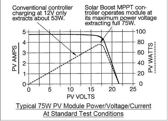
In other words the efficiency of a panel is maximum when its voltage is near the rated specified value. Therefore, as an example a 18V solar panel will operate with maximum efficiency when it's operated at 18V.
And in case the sun light gets weaker and the above voltage drops to say 16V, yet still we could operate it with maximum efficiency if we could keep the 16V volts intact and derive the output without affecting or dropping this voltage.
The below given graph suggests why and how a solar panel produces maximum efficiency when it's allowed to operate at it's maximum circumstantial voltage output.
What's Maximum Power Point or Knee point
Ordinary solar charger controllers only regulate the solar panel voltage and make it appropriate for charging the connected battery, however these do not carry out the panel regulation correctly.
Conventional charger regulator which employ linear ICs for the regulations are unable to keep the solar panel from getting loaded directly by the connected battery or the inverter or whatsoever may be connected as the load.
The above situation tends to drop the solar panel voltage accordingly making its usage inefficient because now the panel is restricted from producing the rated amount of current to the load.
So why does these linear or PWM regulator chargers are unable to avoid loading of the solar panel despite being extremely advanced, accurate and correct with their operations? How do actual MPPT chargers work?
The answer to the above issues is nowhere addressed comprehensively on the net, therefore I thought it necessary to provide with an in-depth explanation regarding the difference between ordinary charger controllers and actual MPPT.
Coming back to the above question, the answer lies in the fact that in linear regulator chargers the load is directly connected with the panel, with no intermediate buffer stage, causing inefficient power transfer and dissipation.
Whereas in MPPT drivers, the load is connected through an intermediate Buck Boost converter which efficiently alters the power conditions to the load depending upon the sunlight power on the panel, ensuring minimum loading of the panel and maximum power delivery to the load.
Basically MPPTs were developed to ensure that the net input wattage was consistently delivered to the output load regardless of the load compatibility with the panel.
How Buck Boost Topology Help MPPT Controllers to maximize Efficiency
This is primarily achieved with the help of a tracking SMPS buck boost technology.
Therefore we can say that it's the SMPS buck boost technology that forms the back bone of all MPPT designs and has provided with an extremely efficient option of configuring power regulation and supplying devices.
In MPPT charger controllers, the solar panel voltage is first converted into a high frequency equivalent pulsating voltage.
This voltage is applied into the primary of a well dimensioned compact ferrite transformer, which generates the required level of current at its secondary winding, matching the specified charging rate of the battery.
The voltage however may not be matching the battery charging voltage, therefore here an ordinary linear regulator is incorporated for fixing the voltage level correctly.
With the above set up the battery stays completely isolated from the solar panel, and gets efficiently charged even under bad weather conditions, since now the solar panel is allowed to operate without affecting or dropping its available instantaneous voltage under any given condition.
This helps to implement the intended maximum power point tracking effect, which is nothing but allowing the panel to operate under minimal loading yet making sure that the connected load gets the complete power required for its optimal performance.
It would be interesting to know how an SMPS prevents the panel or any source from getting loaded directly by the load.
The secret lies behind the use of the ferrite technology. Ferrite transformers are extremely efficient magnetic devices which saturate effectively to generate an efficient conversion from input to output.
Take the example of an ordinary 2 amp iron core transformer power supply and a 2amp SMPS. If you load the two counterparts with full current that is with 2amps, you will find the iron core voltage dropping substantially whereas the SMPS voltage dropping only marginally or rather negligibly....so this is the secret behind the effectiveness of an SMPS based MPPT compared to a linear IC based MPPT charger controller.


Questions & Answers
Thank you Mr Swagatam,
I did find that the power and Voc output of solar panels is very significant, and most good panels provide those specs. Solar panels have a negative temperature coefficient that is from what I heard, is rather linear, but I have not yet tested. The max Voc and Vmp varies based on the solar panel you purchase. I was thinking of making a MPP controller (preset Vmp voltage) instead of a MPPT regulator, but if using a microcontroller the MPPT is free compared to MPP manually set. Simply calculate power once per second or so lol. I also think that most are better off buying a prebuilt MPPT controller instead of making one for higher amperage’s (30 Amps or more). What I am making is more for low current 0.5 – 5 Amps regulation.
-Brad
Thank you Brad, that’s nicely explained, hope the readers will find the information useful for their future ventures
Mr. Swagatam,
Congratulations on having some of the best MPPT information on the internet:)
Do you know where I may be able to find the following information:
1.) I have not seen temperature profiles of Vmp (max power voltage) given Voc (Open Circuit Voltage) for typical solar panels, but heard the Voc increases significantly at lower temperatures. I am trying to find out how much Vmp varies based on temperature.
2.) Same as number 1 but for light variance on a solar panel. How much Vmp varies based on light into the solar panel?
3.) Also related to #2 above, but if a solar panel was angled at 45 degrees away from the light source would you achieve 70.7 percent of the energy?
For an inexpensive, low current (< 2 Amps), MPPT solar regulator, I was thinking of trying to make my own using the following logic, and if you could please comment on how it may be flawed or how it should be done if totally incorrect.
Stage 1: Solar Panel to Buck Converter, PIC MCU controls PWM frequency and duty cycle, but estimating 40KHz PWM frequency, variable duty cycle to maintain max power, but the PIC MCU would manually calculate P=VxI using 2 A-D converters in the PIC and adjust the PWM duty cycle. Mostly it would be like 22V in, 17V out, but I need to find the low current or low light cases as well. The power point would be calculated every second to update the new stage 1 voltage out value (1mv resolution assuming a 16 bit PWM).
Stage 2:) Input is from output of stage 1, typical 17V and regulates down to 12 to 15.6 V depending on input switches for type of battery, state of charge, charging algorithm, but is also a buck regulator using the same PIC MCU for the PWM cycle and a 3rd A-D converter to measure the output voltage, and a 4th A-D converter to measure the output current. Estimating PWM frequency of 80KHz for lower ripple but need to see how many free cpu cycles I have:) Typically, the PIC MCU would run at anywhere around 4 MHz to 40MHz (1-10 Mips), but not sure how fast the PWM's need to actually run? I would use hardware PWM in the PIC MCU, many PIC's have 4 (or more) PWM outputs.
So do you see any faults in my logic? I would of course have fuses on the input, output, and between stage 1 and stage 2. I am an expert at PIC MCU's so this seems easier for me and I know buck regulators ok and have all the parts so kind of free for me, just time and making my own PCB's.
Thank you so much!
-Brad
Thanks Brad,
I have not yet investigated this aspect of solar panels so far. However I think temperature and light should be proportionally linked. If angle is changed to avoid warming up of the panel, this will also affect the light and the electricity proportionately.
The questions that you have asked will need to be analyzed through proper calculations which presently I am unable to do due to work load and pending assignments, and also because my knowledge of microrcontroller is poor.
Hello Swagatam
Your blog is very interesting and varied. Keep it up!
I am also working on smps charge controllers. However, I thought that when the panel voltage is high, you can get the battery to charge at a high rate , say 5 amps, (even though the panel is loaded down) whereas the 14v output from an mppt will put only about 1 amp through the battery. So I am confused about which is better.
Thanks Xavier,
No that's not correct, in fact you have assumed exactly the opposite, if the batt voltage spec is much lower than the panel voltage then it would reduce the amp efficiency of the panel….. in contrast an MPPT would maintain the rate optimally.
Mr Swagatam please remeber that u promise to design for us a mppt that uses the smp transformer technology even if it cannot the iv curve just want to seee the princple. Thank u sir
Mr.Alex I think we can use a buck boost circuit as shown in this article which also is based on SMPS principles for optimizing a solar panel:
https://www.homemade-circuits.com/2013/06/universal-ic-555-buck-boost-circuit.html
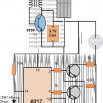
sir please tell me the components you have used in mppt charge controller using IC 555
please click on the diagram to enlarge it, all components are specified in the diagram itself
hello Mr Swagatam as u say the smp mppt is the better design we are kindly asking u to design one and post for us because we cannot find anything on the net to build a high current mppt controller Sir. Thank u
Hi Alex,
No device can increase current more than the source. MPPTs simply make sure that the panel voltage is never dragged down to the battery voltage level, as explained in the above article the idea is to keep the panel free from getting loaded by the battery.
I'll try to produce one suitable circuit soon here.
Please do Mr Swagatam because these mppt controllers are very effective and as u esplained the spms is the typ u need to work on for us . The ones u design I think the charging current only depends on the panel current but these commercial mppt increase the current.. Please help us here sa soon as u can. Thank you Sir for your usual support on circuits
Hello Alex,
I haven't yet figured out the method of tracking and comparing solar panel voltage with battery voltage, once I do it I'll surely post it here.
I'll try to discuss these topics soon in this blog.
Hello Sir,
Thanks for a nice and a very informative artical.
Can you give a SMPS based solar charger circuit for a 12 volt 130AH lead acid battery.
Thanks in advance.
Rashid
Hello Rashid,
I will try to post an smps based solar charger circuit soon.