With a simple design, this 10 watt stereo amplifier circuit offers good dynamics and excellent bass reproduction. Although its power output is modest, at 2 x 10W RMS, it allows for comfortable use in small-sized rooms, such as apartments. When paired with speakers with a minimum power rating of 20W, it will provide complete satisfaction.
Block Diagram
The functional diagram of the amplifier (Figure 1) is quite simple and does not require any specific comments.
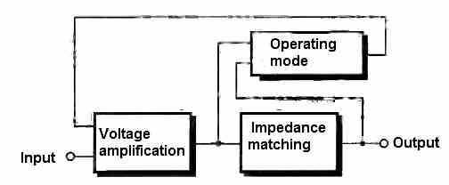
One can notice the possibility to choose the operating mode. This allows the amplifier to work in pure class AB or in feedback-controlled class AB.
The advantage of the feedback-controlled mode is the ability to increase the output power without worrying about thermal runaway of the power transistors.
However, the absence of feedback improves the dynamic response of the amplifier.
Circuit Description
The circuit operation of this 10 watt stereo amplifier circuit can be understood with the following points:
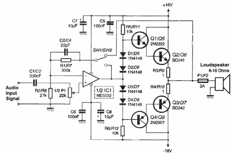
The voltage amplification is achieved by operational amplifier IC1. It is configured as a non-inverting amplifier with a gain of 1 + R1/R2 = 13.2.
The capacitor C1, combined with the potentiometer P1, forms a low-pass filter with a cutoff frequency of F1 = 1/(2πC1P1) = 10.9 Hz.
We also find a high-pass filter formed by C2 and R1, which gives us a cutoff frequency of F2 = 1/(2πC2R1) = 21.9 kHz.
We mentioned earlier that the amplifier can operate in either feedback-controlled class AB or not. The choice is made using the two jumpers SW1 and SW2.
If we connect R1/C2 to R3/R4, the feedback is global; otherwise, it will be local.
With global feedback, it is possible to obtain some additional power, but it requires replacing resistors R3 and R4 (1 Ω 3 W) with 0.1 Ω 1W resistors.
Resistors R5 and R6, along with diodes D1 to D4, help maintain slight conduction in the output transistors. This is class AB operation.
If we decrease the value of these resistors, the bias current of the transistors increases, and we move away from class B operation (which generates the infamous crossover distortion).
Capacitors C5 to C8 are responsible for filtering the power supply voltage, which we will now focus on.
Power supply for the amplifier
A transformer with two secondary windings provides us with voltages of 18V, which will be rectified by the diode bridge P1.
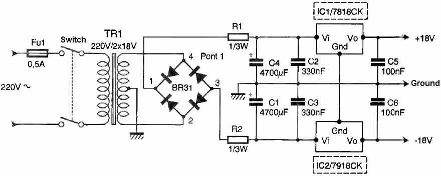
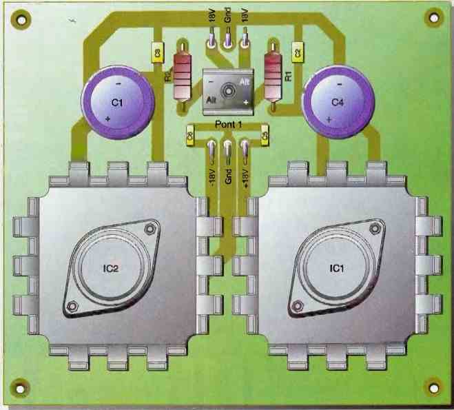
This yields two DC voltages of +24V and -24V, which are stabilized by capacitors C1 and C4.
These capacitors serve as energy storage, while capacitors C2 and C3 are used for filtering out any unwanted noise.
As for resistors R1 and R2, they help limit the current during the initial capacitor charging and maintain a small voltage drop.
IC1 and IC2 are then used to regulate these voltages to +18V and -18V.
Construction
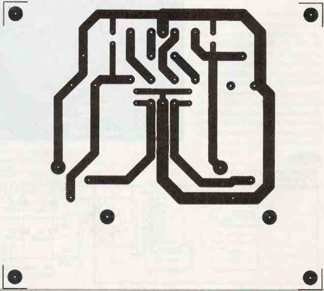
The two input circuits are relatively easy to implement, whether using a photographic method or not.
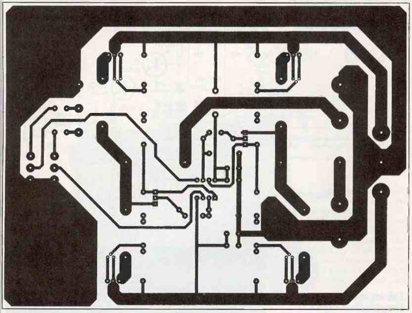
However, it is important to be cautious and avoid narrowing the width of the large traces, as the currents involved in the power circuit can reach several amperes.
We will start by soldering the small components such as jumpers, diodes, and resistors, followed by the integrated circuit and small SMD capacitors.
We will finish with the transistors, fuse holders, power resistors, and the potentiometer. When selecting heat sinks for the power transistors, choose models with a maximum value of 2°C/W.
It is crucial to securely attach the heat sinks to the printed circuit board to prevent damage to the transistor leads from handling and vibrations.
Lastly, do not forget to insulate the power transistors from the heat sink. Use silicone insulators and insulating washers for this purpose.
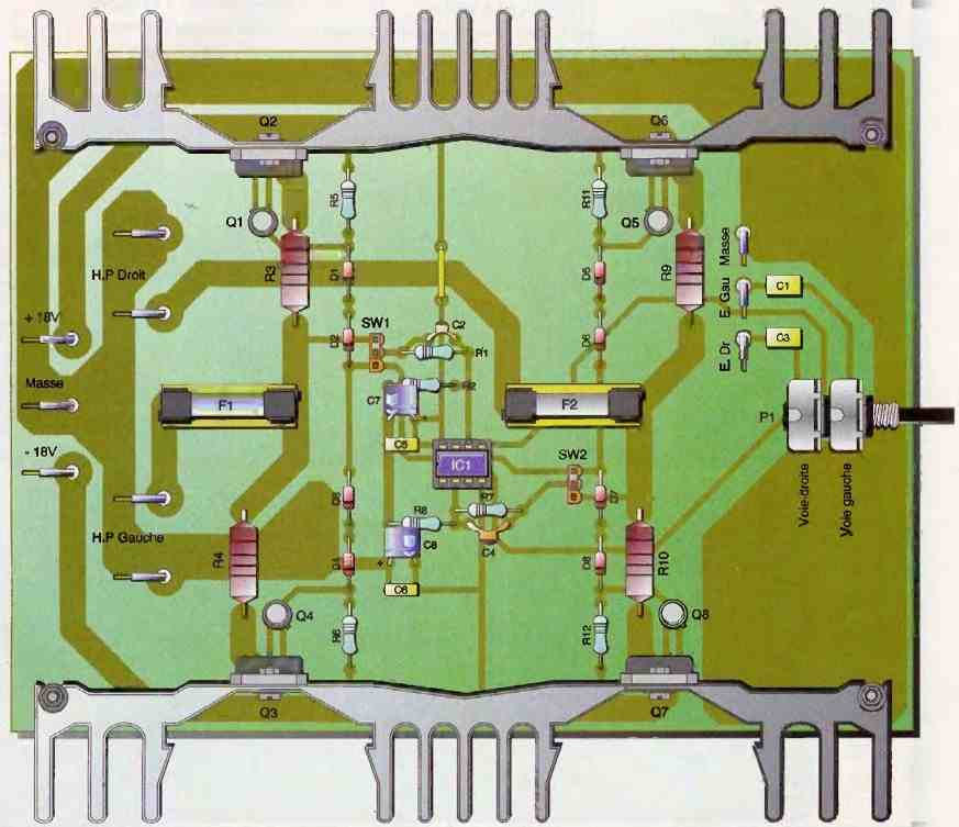
Testing
Double-check the component placement (Figures 5 and 7), the orientation of diodes and capacitors, and ensure that none of the traces are cut or in contact with neighboring ones.
No adjustments are necessary; this 10 watt stereo amplifier circuit can be connected to its power supply and an audio source such as a CD player, and it is ready to operate.
We have measured the following characteristics:
- Bandwidth at -3dB: 11 Hz to 24 kHz
- Input sensitivity: 0.7V RMS for Pmax
- Output power: 10W RMS
- Input impedance: 22 K Ohm


Questions & Answers
I built this circuit a few times, I left out the step down voltage circuit. As I’m running a 80VA 12v centre tap transfomer. Circuit currently runs at 16v which suits the opamp fine. Using a set of tip 31/32 as output transistor. Using a LM833 opamp over the NE5532. I like this circuit a lot as it very simple design with a decent volume and clarity. I will try drop the 1 ohm to 0.1 ohm to up the power 😀
Sounds great! thanks for your interesting feedback, appreciate it very much…keep up the good work…
I’m having trouble hearing my Ham radio since I secured it to the floor of my car under the passenger seat. I want to build a mono amplifier but have no clue how to go about it since all the circuits I find online are for stereo circuits. I can assemble kits but have no clue how to create one. These are the parameters I need the circuit to work under:
A. Input voltage 12-15VDC.
B. I want to build the circuit in a box and the speaker mounted remotely.
C. Needs to work well with voice, not music amplification. — if possible able to adjust voice tone.
Thanks.
WP4TGK
D. C.
Sure! I think the following design is the best one for your application if the IC is available in your area.
Let me know if you have any further doubts regarding the topic:
https://www.st.com/resource/en/datasheet/dm00028077.pdf
A few things I don’t understand in that circuit:
1. why are the components identified as C1/C3 if there’s no C3?
2. What is the purpose of the switch?
3. Are the two resistors before the speakers 1Ω?
4. What wattage should these resistors be?
5. The power supply starts off a 220VAC circuit and it provides the +18VDC for the amp circuit, how can I modify this to make it a step up running off 12-14.5 VDC?
Thanks.
Hi, the following circuit is the one you can try:
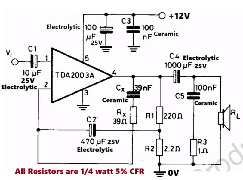
C3 is present in the diagram.
I cannot see any switch, although it can be either used as an ON/OFF switch or an output Mute switch.
R3 is the only one resistor rated at 1 ohm
All resistors can be 1/4 watt 5% CFR
Power supply can be 12V from the battery, no need to step up to 18V.