The main objective we are trying to achieve with this vehicle body metal detector is that only an automobile can trigger the opening of the gate. The solution involving the interruption of a light beam is not suitable, so we turned to a metal detector, as metal is a primary material in any automobile.
In addition to the fact that it is no longer necessary to activate the remote control when you leave your property by car, the advantage of this solution lies in the fact that neither children nor animals can trigger the opening (except by using the traditional means: remote control, push button), which is a significant safety feature as you can manage the availability of these elements as you wish.
Although the amount of metal in a vehicle is significant, the distance between the detection coil (buried in the ground) and the body is not negligible (average of 30cm), which requires the metal detector we have designed for this application to be as sensitive as those used to find treasures.
Block Diagram
The heart of the circuit is based on an oscillator (of the Colpitts type) with coils and capacitors (functional diagram in Figure 1).
In normal operation, when no metal mass is near the coil, the amplitude of the oscillations is constant.
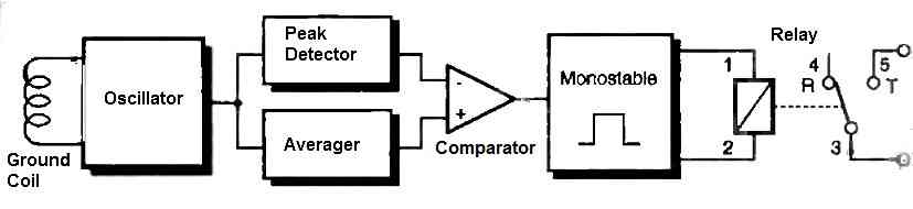
When the metal mass of the vehicle passes near the coil, the magnetic field lines deform, causing a magnetic energy absorption on the oscillating circuit and consequently a more or less significant modification of the oscillations' amplitude.
By detecting this momentary variation of the oscillation amplitude using a comparator, we have information at the output of the comparator, which can activate the opening of the gate by closing the contact of a relay.
One might think that the processing of variations in the oscillation amplitude involves the use of a simple comparator whose switching threshold would be fixed once and for all based on the oscillation amplitude in the absence of a vehicle near the detection coil.
The reasoning is correct, but it ignores the fact that the behavior of an oscillator depends on many parameters, such as temperature.
Variations in temperature modify the bias point of the amplifier designed to compensate for the losses of the tuned circuit so that the circuit can enter and remain in oscillation.
These slow drifts (ambient temperature changes slowly over time) affecting the amplitude of the oscillations led us to use a comparator whose reference threshold reflects the average amplitude of the oscillations.
When a vehicle approaches the coil, the oscillation amplitude varies instantly, while the average value evolves slowly, which unbalances the comparator and triggers the closure of the relay contact.
The duration of the relay closure is limited by the use of a monostable, as can be seen in Figure 1.
Circuit Description
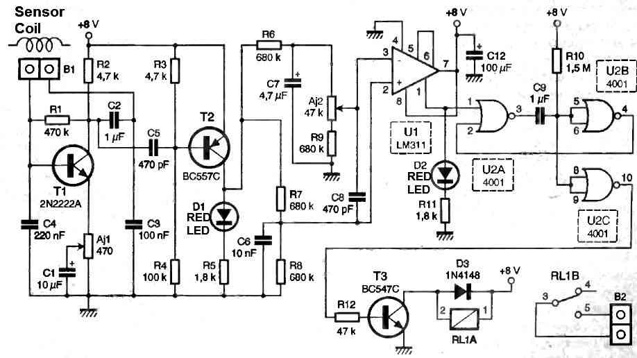
This text describes the structure of an oscillator circuit. The oscillator is built around a transistor, T1, which is partially decoupled in emitter configuration.
The bias point of T1 depends on resistors R1, R2, and AJ1, which make up the amplifier part of the oscillator, while capacitors C3, C4, and the solenoid coil make up the feedback quadruplet, which sets the oscillation frequency.
The oscillation frequency is not critical to the operation of the circuit, but the oscillation itself depends on the value of capacitor C2 and the adjustable AJ1.
The oscillations collected at the collector of T1 are applied to the base of T2 through the capacitive coupling provided by capacitor C5.
Resistors R3 and R4 are chosen to place T2 at the beginning of cutoff, so that T2 will only conduct when T1 oscillates.
The transistor T2 acts as a rectifier, since only the negative alternations of the signal applied to its base can turn it on, given that T2 is a PNP.
The signal present at the collector of T2 is simultaneously applied to the peak detector and the averager, both of which are constructed with resistors and capacitors, with the difference in their behavior mainly due to the different values of the capacitors.
The output voltage of the peak detector, which immediately follows any change in the amplitude of the oscillations, is applied to the inverting input of the comparator, while the output of the averager (which changes slowly, given the time constant of R9, AJ2, and C7) is applied to the non-inverting input of the comparator U1, an LM311.
The result of the comparison is recovered at the emitter of the transistor.
How to Set
In normal operation, AJ2 is set so that the output transistor of the comparator is cutoff, and LED D2 remains off.
The presence of a vehicle near the oscillator coil causes the comparator to switch, turning on the output transistor and illuminating LED D2.
This rising edge is used to trigger the monostable, made up of NOR gates U2A and B and associated with C9 and R10, with NOR gate U2C serving as a buffer. The positive pulse generated by U2C is used to activate the relay coil via transistor T3, closing contact RL1B.
A 78L08 regulator can be used to power the circuit, with a voltage input of 8V obtained from the gate manager, which is typically 12V.
How to Build the Sensor Coil
The sensor coil of this vehicle body metal detector circuit can be built by winding 13 turns of 1 mm thick super enameled copper wire over a circular rigid former having a diameter of 50 cm.
Once the winding is completed the former may be gently removed from the coil and the coil could be rigidly secured using high quality thick insulation tape.
This sensor coil is supposed to be buried underground on the road, so that the when vehicle passes above this coil, it triggers the circuit relay.


Questions & Answers
how does the peak detector and averager circuit work? And can we use this circuit for commercial purpose? thank you.
This circuit was submitted by another author, so i do not have sufficient information about the detailed working of the circuit. Yes you can definitely use it for commercial purpose, but before that you will have verify a prototype design with careful understanding of the concept.