In this post I have explained a random LED number generator circuit consisting of a 4 x 5 LED matrix, numbered from 1 to 20. On pressing a push button these LEDs begin illuminating randomly, until finally a single LED corresponding to a specific number remains illuminated. Thus, this random LED number generator can be used in various gaming or mini gambling applications, just like a roulette game application. By: Salomé
The LED display configuration has 4 rows of 5 LEDs, representing all numbers from 1 to 20. By pressing the push button, two separate time-based counters stop at random positions. The first counter relates to the 5 columns and the second is related to the 4 rows.
The intersection of the column and row thus obtained results in the corresponding LED being lit up.
Circuit Description
Power Supply: The random LED generator circuit operates with a 9-volt battery that can be turned on using the switch I.
The capacitor C1 ensures better stability of the power potential, especially during counting/activation cycles. As for capacitor C2, its role is to decouple the power supply from the circuit itself.
Time base of the counter assigned to the columns.
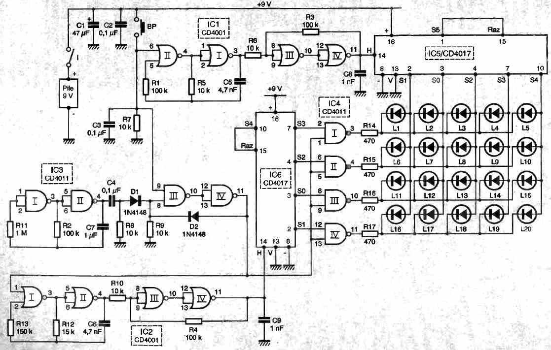
The NOR gates I and II of IC1 form a controlled astable oscillator. As long as the push button BP is not pressed, the oscillator "runs" continuously, delivering a square signal on its output characterized by a period of around 100 ps, which corresponds to a frequency of 10 kHz.
The trigger constituted by gates III and IV of the same integrated circuit gives these signals rising and falling edges characterized by a more vertical shape and therefore more suitable for incrementing a counter.
As soon as the push button is activated, the oscillator is blocked and presents a high level signal on its output.
Controls of the outputs assigned to the columns
The integrated circuit IC5 is a CD 4017. It is a decimal counter-decoder that advances one step for each rising edge on its CLOCK input (pin 14). Since the RAZ (Reset) input is connected to output S5, the counter can only occupy positions S0 to S4.
Thus, it is on one of these 5 outputs, connected to the anodes of the 4 LEDs configuring each column, that a high state will be available as soon as the push button is pressed.
Operation of the Timer Counter's Row Time Base Control
The NAND gates I and II of IC3 form a permanent astable oscillator. This oscillator produces a square wave signal with a period of approximately 220 milliseconds.
The rising edges of this signal are processed by a differentiator system consisting of C4, R8, R9, and D1. As a result, brief positive pulses of the same period appear at the anode of D1. The NAND gates III and IV of IC3 are configured as latch gates.
As long as the input 9 is at a low level, which is the general case thanks to the presence of R7, the output of this latch gate remains low.
However, when the pushbutton is pressed, the output switches to a high level, but with a completely random delay of 0 to 220 milliseconds.
To obtain a high output on this latch gate, it is necessary to wait for a positive pulse transmitted by D1, which locks the output of the latch gate in a stable high state thanks to D2. This situation persists as long as the pushbutton is held down.
Thanks to this technique, a random delay is introduced before locking the time base of the counter assigned to the rows after the pushbutton is pressed, as we will see later.
This arrangement further increases the randomness of the outcome by preventing any relationship between the locking positions of the first and second counters.
Timebase and control of counter outputs affecting the rows
The NAND gates I and II of IC3 also form an astable oscillator whose operation is permanent as long as the push button is not pressed.
The square wave signals generated are characterized by a deliberately different period from the NOR oscillator I and II of IC2, always with the aim of increasing the randomness of the draw.
This period is approximately 150 microseconds, or 6.6 kHz. The NOR gates III and IV of IC2 are set up as triggers.
We saw in the previous paragraph that the output of the memory device presented a high state with a certain delay once the push button was pressed. It is after this random delay that the astable oscillator is locked.
Controls of outputs affecting the rows
Counter IC6 is also a CD 4017 advancing by one step at the rate of the rising edges delivered by the trigger output. This counter can occupy only one of the 4 positions S0 to S3, since the reset input is connected to S4.
When the oscillator mentioned in the previous paragraph is locked, a high state is then detected on one of the 4 corresponding outputs.
Display control
As long as the inputs (1, 5, 9, and 13) of the four NAND gates I to IV of IC4 are at a low state, their outputs are high. No LED can turn on in this case.
However, as soon as the NOR oscillators I and II of IC2 are in a locked state, these inputs are set to a high state.
This results in a low state on the output of the NAND gate that is opposite to the high output S of IC6.
This results in the LED at the intersection of the column and row defined by the locked positions of the two counters to turn on. Resistors R14 to R17 limit the current consumed by the LED.
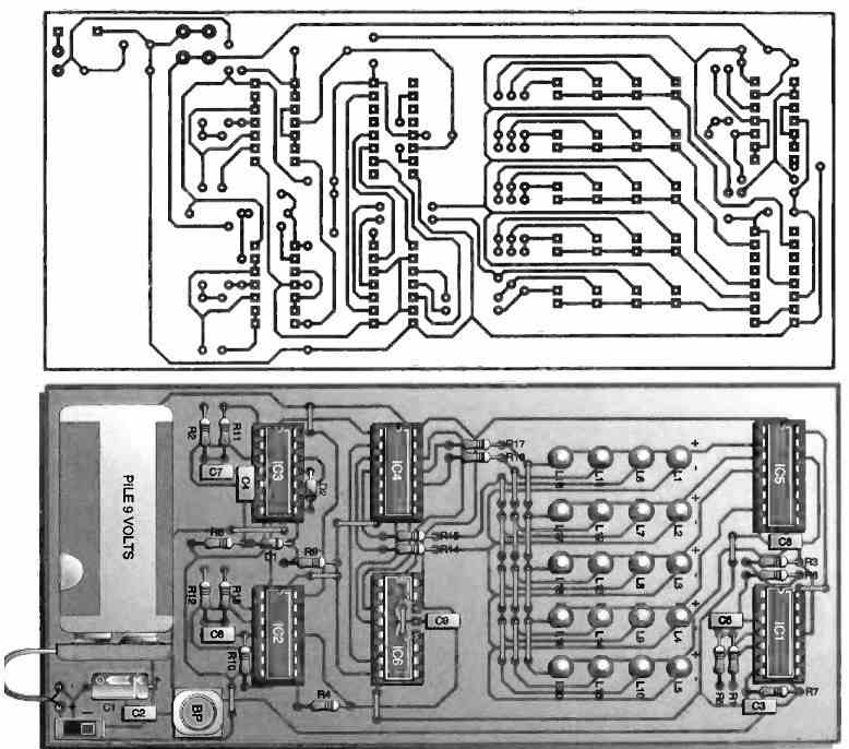
Construction
Figure 2 below shows the printed circuit board of this random LED generator schematic. There are few remarks to be made on this subject.
Figure 3 provides the component placement plan. Pay attention to the orientation of the polarized components. The assembly does not require any adjustments.
Before concluding this functional description, let us ask ourselves the question of the number of chances to obtain all 8 numbers.
The principle of this probability calculation is as follows. It is as if we had a bag containing, for example, 20 numbered balls from 1 to 20.
For the first draw, the chances are 8/20. For the second draw, they are 7/19, for the third 6/18, and so on. Ultimately, the number of chances is calculated by the formula: 8/20 x 7/19 x 6/18 x 5/17 x 4/16 x 3/15 x 2/14 x 1/13 = 1/125970.
But let us not be discouraged by this mathematical speculation and rather trust our assembly to see Lady Luck smile.


Questions & Answers
I would like please to see a PCB for this project if some friend could to do it.
Cool circuit. One question
Under the heading Timebase and control of counter outputs affecting the rows
you say
“The square wave signals generated are characterized by a deliberately different period from the NOR oscillator I and II of IC1.”
Do you mean IC2? Because IC1 is concerned with the columns but that paragraph is talking about the rows.
You are right, it looks like it should be IC2, to make sense.
Thanks for notifying the issue, I have updated the info accordingly…
Thanks for the quick response. I’m making a pcb for this circuit. If you can provide the gerber files next time that would be immensely helpful.
Thanks for your work
You are most welcome! Actually the above article was submitted by an external author, and I did not get a gerber file from him. I wish I could get it. I hope you can get it done from a professional PCB designer. Please let me know how it goes?
Random LED Number Generator for Gambling Application:
Hello Swagatam. One question: Is there any video available about this wonderful circuit? I would like very much to rebuild it on my own with PCB but I have no idea how the LEDs will show up when power is connected. Thank you very much for all your circuits and for sharing it to us all!????????
Regards, Boris ????????
Thank you Boris, Glad you liked the post!
However, presently I do not have the video of this circuit.
According to my guess, when power is connected, all the LEDs should start and keep illuminating randomly.
Once the push button is pressed, all the LEDs should begin shutting off randomly, one after another, until finally only one LED remains illuminated..