• Skip to main content
  • Skip to primary sidebar

Homemade Circuit Projects

Need circuit help? Post them in the comments! I've answered over 50,000!

Blog | Categories | About | Contact | Calculators-online
You are here: Home / Power Supply Circuits / Transformerless Relay Driver Stage

Transformerless Relay Driver Stage

Last Updated on January 2, 2024 by Swagatam 8 Comments

In this post I have explained an enhanced transformerles power supply circuit design which consists a well stabilized and regulated DC stage along with a relay driver stage which operates through an external pulse. he idea was suggested by Mr. Reza.

Table of Contents
  • Technical Specifications
  • Circuit Operation:
  • Modifying the Circuit for 220V Operation
  • Circuit Diagram

Technical Specifications

Reza: Dear Sir, I have a problem with one Circuit regarding converting an Ac 110v power supply to 220v or 250v AC. But I am unable to do it.

You’re Blog Site and your Circuits make Me crazy, really you are an Electro Man. My Interest is growing  more and more with every visit to your site. This has inspired me to solve my problem with your help.

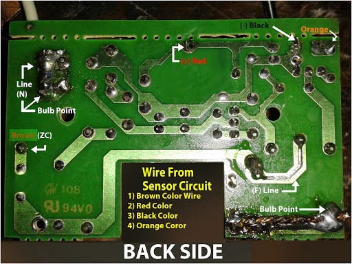
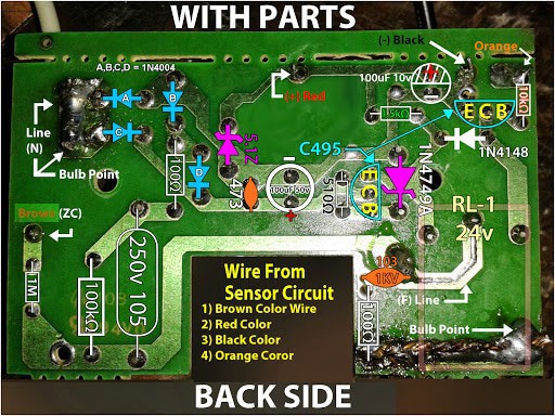
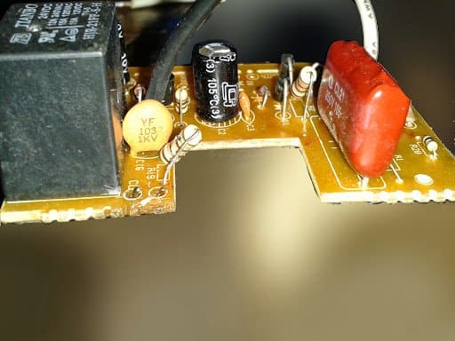
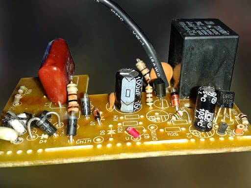
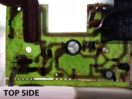
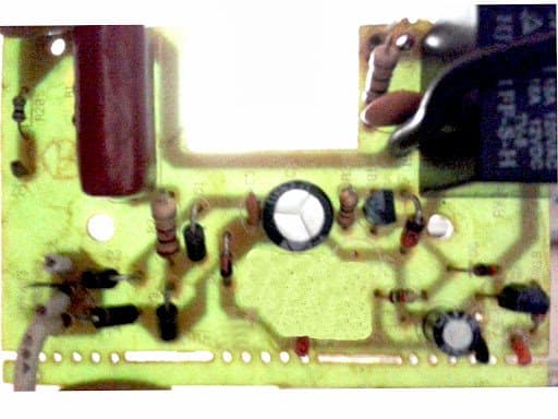
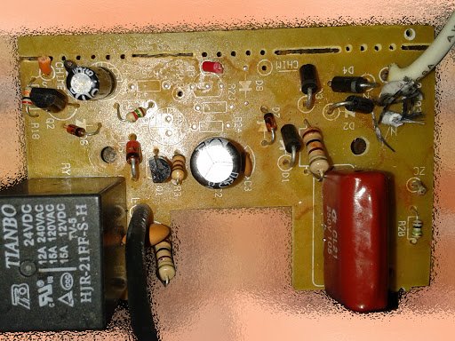
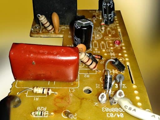
So, I need to send you some pictures of that circuit which I want to convert from AC 110v to 220v up 250v AC Main Line.

Sir I am waiting for your response. Simply should I change the 105-250v Capacitor and two Resistors that are 100kΩ and 100Ω or something more than that.

But I am confused regarding what is the real one for 220v up to 250v. For your information I have changed the 200watt Halogen Bulb too.

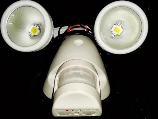
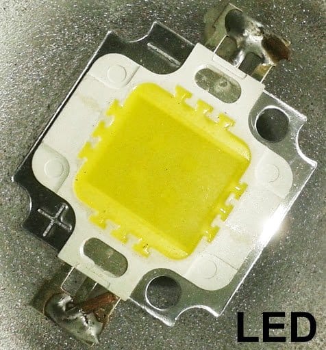
I have used two square sizes LED (Per Bulb head) and the extra 5volt Mobile Charger Adapter power source for my LEDs, and connected with RL1.

My Response:

Can you specify what exactly are you trying to build?

Reza: I am building nothing. Trying to convert my 110v motion sensor device to220v AC. That's all
But I am not sure with the procedures. That's why i need your help sir, it is transformerless power circuit board.

Circuit Operation:

Before we modify the design for 220V application, let's first understand the functioning of this upgraded transformerless power supply with relay changeover trigger circuit through the following discussion

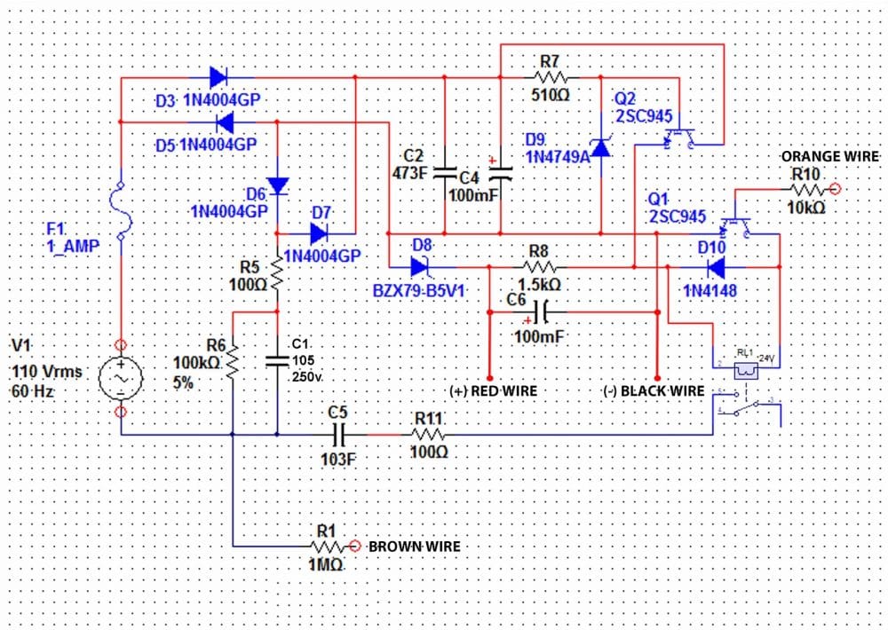
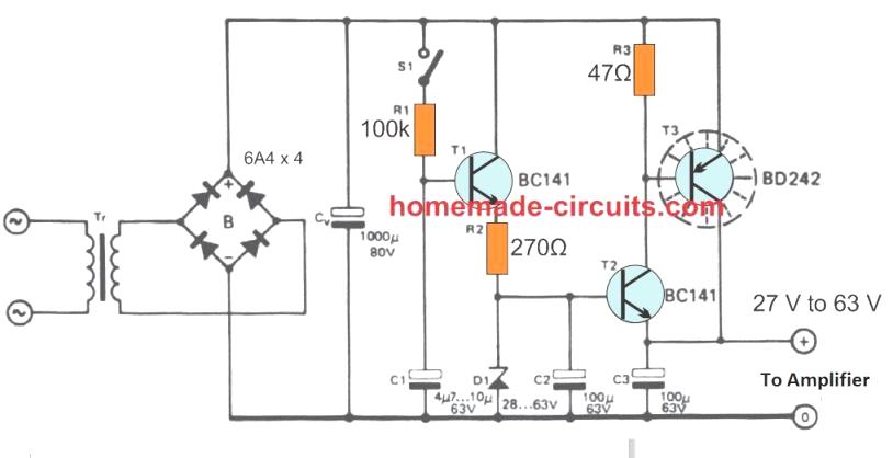
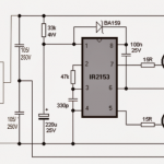
Referring the diagram given below, the various parts can be categorized with the following operations:

C1 = High voltage capacitor for stepping down the mains current to tolerable circuit limits.
D3, D5, D6, D7 form the basic bridge rectifier stage.

C2, C4 are for filtering the spikes and the ripples from the DC components.

Q2 forms the emitter follower with its base clamped at 24V by the zener diode D9 and R7.

Being an emitter follower, the voltage at emitter also will be equal to the base voltage, that is 24V and current equal to the combined value of base and collector.

This +24V emitter output is applied to the 24V relay via Q1. When Q1 is triggered from an external positive source via R10 (orange wire), the relay activates.

R8 and D8 connected to the emitter of Q2 forms an additional 5V stabilized output, may be for some specified purpose across the shown RED wire.

R5 is used for included for restricting switch ON surges, while R6 for discharging C1 whenever the system is unplugged from mains.

Modifying the Circuit for 220V Operation

As requested by Mr. Reza, the circuit needs to be modified so that it can safely operate even with 220V supplies, however a close look reveals that except C1 voltage everything seems to be in order and well suited for voltages right from 110V to 300V.

So, C1 should be changed to 105/400V, and may be R7 should be tweaked a bit or its wattage increased to some higher level and R6 raised to 1M, rest everything looks perfect and well organized.

Circuit Diagram

warning message: electricity is dangerous, proceed with caution
Main2BPower2BSupply2BCircuit2BBRINKS2BModel2BNo 2B7011W2B2528Security2BLighting2BSystem2BMotion2BActivated2B200watt2BHalogen2BBulb2529
20131007 181744
1
2 1
BACK
FRONT 2
TOP2BSIDE2BCOPER2BBACK2BPREVIEW2B 2B1
TOP2BSIDE2BCOPER2BBACK2BPREVIEW2B 2B2
TOP
LED
LEFT

You'll also like:

  • 1.  Modifying XL4015 Buck Converter with an Adjustable Current Limiter
  • 2.  IC 7805 Variable Power Supply Circuit [5V to 15V]
  • 3.  SMPS 50 watt LED Street Light Driver Circuit
  • 4.  How to Design a Flyback Converter – Comprehensive Tutorial
  • 5.  0 to 50 V Adjustable Switching Power Supply Circuit using IC LM2576
  • 6.  Connecting Voltage Regulators 78XX in Parallel for High Current

About Swagatam

I am an electronics engineer with over 15 years of hands-on experience. I am passionate about inventing, designing electronic circuits and PCBs, and helping hobbyists bring their projects to life. That is why I founded homemade-circuits.com, a website where I share innovative circuit ideas and tutorials. Have a circuit related question? Leave a comment.... I guarantee a reply!

Previous Post: « Simple Adjustable Industrial Timer Circuit
Next Post: 12V, 24V, 1 Amp MOSFET SMPS Circuit »

Reader Interactions

Comments

  1. sedigh hosein says

    September 5, 2019 at 4:35 am

    hi swagatam i dont know thate weither my comment are visible for you ???

    Reply
    • Swagatam says

      September 5, 2019 at 9:44 am

      Hi Sedigh, once the comment is posted it will reach me without fail, so you can rest assured you will get the replies.

      Reply
  2. sedigh hosein says

    September 5, 2019 at 4:28 am

    hi dear sir swagatam majomdar i would like to know most about transforless circuits for using to atmaga chip with fully protection and also useing an ic 7805 in outlet circuit excuse me concern poor english
    weather you can suggest me an circuit about this
    with best regards

    Reply
    • Swagatam says

      September 5, 2019 at 9:45 am

      Hi Sedign, I am sorry I do not have this circuit presently using Atmega chip

      Reply
  3. sedigh hosein says

    September 5, 2019 at 4:08 am

    hi swagatam majomdar can i use of an 7805 in output the circuits that are transforless???

    Reply
    • Swagatam says

      September 5, 2019 at 9:47 am

      Sedign, a 7805 can be applied after a 24V zener diode, or through a MOSFET regulator

      Reply
  4. Shrikant Dhone says

    December 16, 2015 at 5:13 pm

    Hi swagatam
    I constructed the ckt for 24v relay but it works only for few minutes
    what is the reason. most of the ckts work only for few minutes
    i used 1n4007 diodes
    please help me

    Reply
    • Swagatam says

      December 17, 2015 at 11:06 am

      Hi Shrikant, It'll be difficult for me to judge the fault without actually seeing it, can you tell me what exactly are you trying to build or implement with the design? I could suggest an alternative and easier circuit.

      Reply

Need Help? Please Leave a Comment! We value your input—Kindly keep it relevant to the above topic! Cancel reply

Your email address will not be published. Required fields are marked *

Primary Sidebar

Subscribe to New Circuit Ideas

Categories

  • Arduino Projects (87)
  • Audio and Amplifier Projects (132)
  • Automation Projects (17)
  • Automobile Electronics (101)
  • Battery Charger Circuits (83)
  • Datasheets and Components (104)
  • Electronics Theory (143)
  • Free Energy (37)
  • Games and Sports Projects (11)
  • Grid and 3-Phase (19)
  • Health related Projects (25)
  • Home Electrical Circuits (12)
  • Indicator Circuits (14)
  • Inverter Circuits (87)
  • Lamps and Lights (142)
  • Meters and Testers (69)
  • Mini Projects (46)
  • Motor Controller (64)
  • Oscillator Circuits (27)
  • Pets and Pests (15)
  • Power Supply Circuits (108)
  • Remote Control Circuits (50)
  • Security and Alarm (64)
  • Sensors and Detectors (101)
  • Solar Controller Circuits (59)
  • Temperature Controllers (42)
  • Timer and Delay Relay (49)
  • Transmitter Circuits (29)
  • Voltage Control and Protection (37)
  • Water Controller (36)

Calculators

  • Battery Back up Time Calculator
  • Capacitance Reactance Calculator
  • IC 555 Astable Calculator
  • IC 555 Monostable Calculator
  • Inductance Calculator
  • LC Resonance Calculator
  • LM317, LM338, LM396 Calculator
  • Ohm’s Law Calculator
  • Phase Angle Phase Shift Calculator
  • Power Factor (PF) Calculator
  • Reactance Calculator
  • Transistor Astable Calculator
  • Transistor base Resistor Calculator
  • Voltage Divider Calculator
  • Wire Current Calculator
  • Zener Diode Calculator
  • Filter Capacitor Calculator
  • Buck Converter Calculator
  • Boost Converter Calculator
  • Solar Panel, Inverter, Battery Calculator
  • Wire Current Calculator
  • SMPS Transformer Calculator
  • IC SG3525, SG3524 Calculator
  • Inverter LC Filter Calculator

People Also Search

555 Circuits | 741 Circuits | LM324 Circuits | LM338 Circuits | 4017 Circuits | Ultrasonic Projects | SMPS Projects | Christmas Projects | MOSFETs | Radio Circuits | Laser Circuits | PIR Projects |

Recent Comments

  • Swagatam on Adjustable 0-100V 50 Amp SMPS Circuit
  • ibrahim on Adjustable 0-100V 50 Amp SMPS Circuit
  • Swagatam on Contact
  • KRAB Babu on Contact
  • Swagatam on How Shunt Regulator TL431 Works, Datasheet, Application

Company

  • Privacy Policy
  • Cookie Policy
  • About Me
  • Contact
  • Disclaimer
  • Copyright
  • Videos
  • Sitemap

Social Profiles

  • Twitter
  • YouTube
  • Instagram
  • Pinterest
  • My Facebook-Page
  • Quora
  • Stack Exchange
  • Linkedin
  • © 2025 · Swagatam Innovations