The 10 km range, 27 MHz transmitter circuit explained here uses citizen's band which consists of 2 main types of users: radio control (R/C) modellists and users of low-power FM transceivers for local communication.
However, here it is designed and intended for testing antennas and aligning receivers. It is actually an AM/FM quartz controlled for getting the best frequency stability, and contains an RF output power of about 0.5 watt. Driven by a 12-V supply, it might be ideal for mobile and portable use.
Contributed By: Eric Fernandeiz
Circuit description
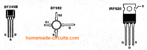
The circuit diagram (Fig. 1) indicates a typical 3-transistor transmitter layout using FETs (field-effect transistors).
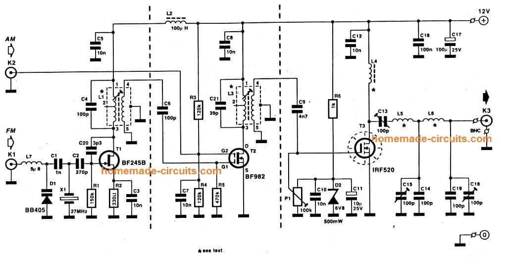
The oscillator developed around FET T1 gets its frequency solidity through a quartz crystal, X1. Here, an low-cost third-overtone series resonance crystal is employed.
The oscillator is ‘forced’ to run on the third over-tone of the quartz'crystal by fine-tuning the L-C parallel tuned circuit from the drain line to 27 MHZ.
Capacitor C20 is necessary to guarantee satisfactory feedback in the oscillator, as well as boosts its start up actions.
Frequency modulation in a low deviation (NBFM) is accomplished using a adjustable capacitance diode ('varicap’), D1. The audio input signal (150 mVpp max.) is supplied to connector K1.
The oscillator signal activated on the secondary winding of L1 is given to the gate-1 terminal of MOSFET T2, a BF982.
Gate 2 of T2 is fixed at approximately 50 percent of the supply voltage through R2-R3 to attain highest amplification.
If AM [amplitude modulation; pretty uncommon though) is necessary, the modulation signal could be attached to K2 using a coupling capacitor. The audio voltage may alter the gate 2 voltage of the MOSFET, resulting in linear [within limits!) gain control of the MOSFET.
The result is an amplitude-modulated RF output signal. An sound level of 130 mVpp leads to a modulation depth of around 70 PERCENT.
The quiescent current of the power amplifier transistor, T3, is defined using the preset P1, which establishes the gate bias.
Observe that the preset's supply voltage is intensely decoupled to protect against supply and zener diode noise interfering'with the RF signal on the gate. The RF power transistor is a HEXFET® Type IRF52O from International Rectifier. As presented, the transistor is thermally controlled with a heatsink.
The output filter is a basic pi-type low-pass created to minimize harmonics and complement the output transistor into a load of 50-Q, that is plugged into K3.
Construction
The building of the transmitter is ideally begun by making the inductors. Very first, pay attention to the coupled inductors, L1 and L3. Examine their positioning on the PCB to ensure that the primary and secondary windings navigate to the proper base pins.
Inductor Winding details
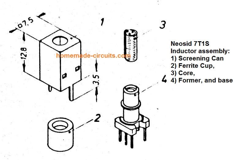
- L1: wound on Neosid 7T1S core.
- Primary (1-3) = 8 turns; secondary (4-5) = 2 turns. Wire: enameled copper, 0.2 mm dia. [SWG36).
- L3: wound on Neosid 7T1S core.
- Primary (1-3) = 10 turns; secondary (4-5) = 2 turns. Wire: enameled copper, 0.2 mm dia. (SWG36].
- Take the help of an ohmmeter to test the continuity of the windings on the base pins.
- You should not mount the ferrite cup and the screening cap at this moment (Fig. 2). We carry on with the inductors in the power output amplifier.
- L4 consists of 3 turns of 1-mm dia.
- [SWG20) enamelled copper wire through a 2-hole ferrite balun bead.
- As pointed out in the PCB overlay, this inductor is installed vertically.
- L5 includes 12 turns of 1-mm dia (SWG2O) enameled copper wire.
Closely wound internal diameter 8 mm; no core. L6 is made up of 8 turns of 1-mm dia. (SWG20] enameled copper wire. Tightly wind internal diameter 8 mm; without core. The PCB layout is supplied in Fig. 3.
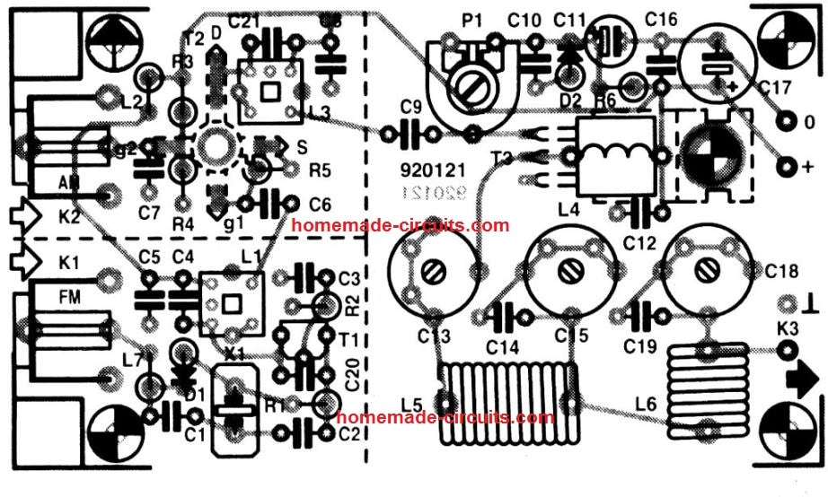
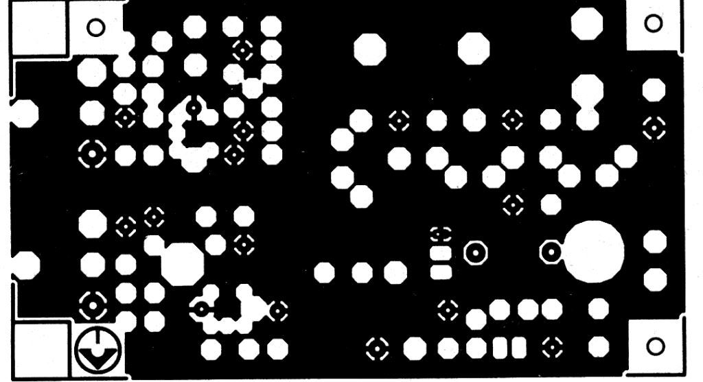
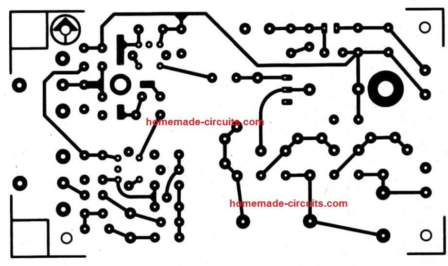
lt must be taken into consideration that the board for 27 MHz transmitter circuit is double sided, but is not through-plated.
This implies that component leads has to be soldered from both sides of the PCB wherever applicable. Furthermore, each and every part wires should be kept as small as feasible.
Commence by fitting inductors L1 and L3. Do not install the screening boxes as yet. As suggested by their dashed lines on the PCB overlay.
Transistors T2 and T3 are fixed at the bottom side of the PCB. This allows T3 to be safely placed to the base of the metallic housing where the PCB is fixed later on. Remember to apply an insulating washer, because the metal tab of the IRF520 is coupled to the drain.
The type hint of T2 is legible from top area of the PCB. The rest of the engineering is pretty basic, and should not bring about difficulties for those who have some expertise in developing RF or radio projects.
The audio input sockets are PCB-mount types. The oscillator, buffer and power amplifier are shielded from each other by bits of 15-mm large tin sheet fixed top to bottom on the dashed lines around the PCB overlay.
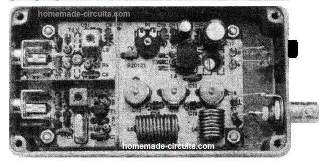
As indicated in the opening picture of the prototype, the board is set up in a diecast enclosure.
Despite the fact that a BNC socket is used on the prototype, an SO-239 style is likewise well suited for the RF output. The DC power supply input is created with a 2-way adapter outlet as utilized on portable radios.
How to Setup
You will require the below mentioned tools to fine-tune the transmitter:
A frequency meter or a grid-dip meter, a dummy load or an in-line SWR/power meter.
An isolated trimming screwdriver and a regulated 12-V power supply. Attach a little TO-220 style heat-sink to the tab of T3.
Initially, flip the wiper of P1 to ground side, and set the 3 trimmers close to midway. Carefully place the cores in L1 and L3.
You don't need to implement a modulation signal at this moment of time to any of the inputs.
Switch ON power, and pair the frequency meter or GDO inductively to L1. Fine-tune the core until the oscillator starts operating at the quartz crystal frequency.
Switch off and ON once more to examine the initialization of the circuit. Next, go to L3, and adjust the core for resonance at 27 MHz. This is quickly assessed by shifting the pick-up system a little far from the inductor.
In case you cannot apparently identify a precise optimum (‘peak‘) by doing this, don't be upset, since this is just a casual realignment. After this, , cautiously watch the current utilization of the transmitter.
With care adjust P1 so that the current drain is not more than 100 mA, and observe the output power.
Maximize the three trimmers for getting peak output power.
The trimmer tweakings may interfere somewhat, which means you might have to devote a few minutes until the best adjustments are identified.
After that, tweak L3 for maximum output power. Lastly, fix the ferrite cups and the screening cans on L1 and L3.
After removing the temporary heat sink on T3, the finished board can be fixed into the housing. This is completed with the help of PCB spacers and bolts, for which you will find 4 PCB corner slots.
T3 is fixed onto the base of the box with the help of mica washer. The bolt can be gotten through the hole in the PCB. Take the help of an ohmmeter to test if the tab of the transistor is out of the way from the diecast enclosure.
Finally, guarantee that preset P1 is adjusted to lowest PA current drain (wiper completely to ground) prior to feeding an AM modulation signal. Cautiously adapt P1 to have an output power of approximately 0.5 W PEP (peak envelope power) directly into a 50-Q load.
Caution
The 27-MHz transmitter band or Citizen's Band includes 2 primary groups of users: radio control (R/C) modellists and users of low-power FM transceivers for local communication. The devices utilized by the teams is governed by certification by the national PTT authorities (Department of Trade and Industry in the UK). The certification is co-ordinated at an worldwide level by the CEPT (Commission Europeenne de Postes et Telegraphe), while the frequency allocations are given by the WARC (World Administrative Radio Conference). In many European nations you do not have to pass an examination to acquire a CB license. Having said that all CB transceivers has to be type-approved, and may not be customized by any means. Furthermore, you will find stringent polices in relation to broadcast power, modulation type (narrow-band FM), antenna size and frequency use. The majority of CB communication is short- range (usually up to 10 km), and focused in and around big metropolitan areas and on motorways, mobile communication being granted also.


Questions & Answers
Hi there, just discovered your site and really like it. I thought I would share some info on the 27Mhz CB band in the United States. Our band is controlled by the F.C.C. (Federal Communications Commision). We used to need licenses for the CB band but, that requirement was done away with many years ago. The Frequencies are shared much like where you are from, RC operators and Citizen Band Radio operators. Our range of “Legal” channel frequencies go from 26.965 Mhz through 27.405 Mhz. IE: channels 1-40. I put the term Legal in quotes because a lot of people will mod their radios to go below or above the frequencies (Free banders). We are not restricted to FM for modulation though. We have AM-FM-Upper Side Band (USB)-Lower Side Band (LSB or just SSB when talking about both) Our power limits are 4 Watts (AM), 4 Watts (FM) and, 12 Watts PeP (SSB). Of course just like with Free-Banders, there are many who go well above those limits. Most of the time the F.C.C. doesn’t bother people about any of it unless they start getting a lot of complaints from people about interference. Then you get a visit from “Uncle Charlie” which usually ends with confiscation of all your equipment, huge fines and in some cases, prison time. CB died out for a while but is starting to make a big comeback here. Instant communication without waiting for a signal and the fact the Government can’t flip a switch and stop you from communicating are the two biggest reasons. Hope you found this info useful!
Thank you Todd, for this interesting information…. much appreciated..
How to use encoder and decoder with 27 mhz transmitter and receiver.
I mean pairing.
The above circuit is an RF based circuit so encoder and decoder is not required, it works with modulator and demodulator instead.
You will need two of these modules across the two ends to communicate, which work both like a transmitter and a receiver.
Hi, nice post, I would like to replicate this transmitter but I have some questions with the inductors, for example, L1 & L3, I haven’t Neosid 7T1S core, only Amidon cores, but I would like to know those inductances values, also with L4 needs ferrite balun bead, do you know where can I buy or how can I replace with another core.
Hope you can help me.
Regards.
Hi, thanks for liking the post! However,sorry, inductance values are not available with me, only the turn details are available.
You can buy the cores from any online electronic spare part store.
do you have YouTube channel you have demonstrated that idea?
Sorry, I do not have a video for this!
Very good sound.Perfect modulation.
İ do this transmitter for 17 mt band sw
Thank you for updating the information. Glad it worked for you!
Hi,
Thank you for your work!
Has this circuit been tested?
If not can you confirm that it should work another way?
Hi, You can see the prototype image at the beginning, which confirms that it is tested
Good morning ENGR. I’m having challenges here on circuit above…I couldn’t get most components here in Nigeria, especially all the bf components,,is there any equivalent or another transmitter circuit diagram you have 10km range and above.
Hi Sunshine, you must start building this design only once you have access to all the exact parts and PCB. Any form of alteration or modifications may cause issues or not allow the circuit to work correctly. sorry I do not have any other easier 10km design.
I am interesting in your site specifically ; when you explained the circuits working with good explanation.
Thanks for you
Thank you Amer, appreciate your thoughts.
I want to purchase this completed tested and working transmitter.
Let’s chat through my email
Sorry, I don’t sell readymade kits in this website!
Yes, I am interested in RC mainly in Citizen Band as I am staying in India.