• Skip to main content
  • Skip to primary sidebar

Homemade Circuit Projects

Need circuit help? Post them in the comments! I've answered over 50,000!

Blog | Categories | About | Contact | Calculators-online
You are here: Home / Security and Alarm / Make this SleepWalk Alert Circuit – Protect yourself from Sleepwalking Dangers

Make this SleepWalk Alert Circuit – Protect yourself from Sleepwalking Dangers

Last Updated on November 15, 2023 by Swagatam Leave a Comment

Do you have a habit of walking in night? Well, that habit isn’t that good, so one must try to get rid of it gradually. This article discusses a simple sleep walk alert circuit that might help you in getting out of this habit.

Table of Contents
  • Circuit Objective
  • WORKING OF THE CIRCUIT:
  • MAKING THE PRESSURE SENSOR:
  • USING THE ARRANGEMENT:

By: SS Kopparthy

Circuit Objective

This circuit is a simple idea of warning a person who is using this when they try to get down the bed by vibrating an small DC vibration motor attached to the person’s leg so that the person can be awakened due to vibrations and can get back to bed.

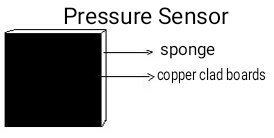
The sensor used to detect that person is out of bed is a pressure sensor that is home made using two square copper clad strips of side 6.5cm and a sponge of 2.5cm width placed between the copper strips.

This arrangement acts as a variable capacitor and the capacitance changes when the pressure applied on it changes and this is used to trigger IC 555 and vibrate the vibration motor through simple circuitry.

pressure sensor using two square copper clad strips of side 6.5cm and a sponge of 2.5cm width placed between the copper strips

WORKING OF THE CIRCUIT:

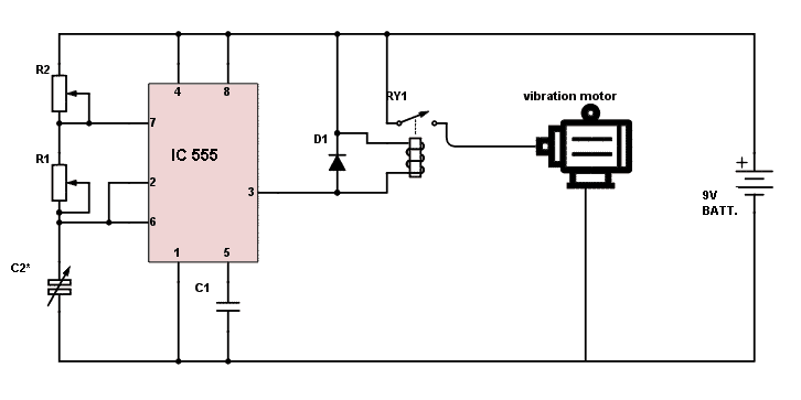
The sleep walk alert circuit consists of a IC 555 which is heart of the circuit. Here the IC 555 is wired as a astable multi vibrator.

The pressure sensor used works as a variable capacitor and its capacitance varies when the pressure is applied. When no pressure is applied, the capacitance of the capacitor is less than 10pf.

When pressure is applied, the distance of separation between the copper clad strips capacitance is around 50pf.

This happens because the capacitance of a parallel plate capacitor is inversely proportional to distance of separation of the plates.

Now, this variation in the capacitance makes the IC to trigger itself and the output at pin #3 of the IC goes high.

This is connected to a relay whose contacts are used to run the vibration motor.

IC 555 pressure activated switch circuit

MAKING THE PRESSURE SENSOR:

You need two copper strips (6.5*6.5 length*breadth, applied with varnish and cleaned), a thick new sponge of 2.5cm thickness, two ordinary insulated flexible wires and a little amount of glue to stick the sponge between copper strips.

Take the copper strips and place the sponge between them and stick the sponge to the copper strips by gluing only on the sides.

REMEMBER NOT TO GLUE IN CENTERS OF SPONGE OR STRIPS AS IT MAY DISTURB THE SENSOR AND YOU MAY NOT GET DESIRED OUTPUT.

After the glue gets dried, solder the insulated flexible wires to both the copper strips. You’ve completed making the sensor now.

Just connect the wires to the circuit according to the circuit diagram.

USING THE ARRANGEMENT:

Take the circuit and enclose it in a suitable plastic casing. Also stick the vibration motor inside the plastic case using m-seal or any such.

Connect the circuit to a 9V battery and put the battery into the same plastic case as well. Put a small hole to the casing for the wires of sensor to come out of the case.

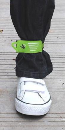
Now, take the pressure sensor and stick it to the bottom of a new sandal. Also, the plastic case containing the circuit, vibration motor and the battery is fitted to the a leg strap and the strap is worn above the ankle.

The strap and sandals are to be worn just before sleeping, so that is you get down the bed, it vibrates and you will be awakened.

A leg strap like the one shown in the image below can be used.

leg strap assembly

This might help you out in getting out of the habit of walking in sleep. But it is not an medical alternative. Good luck!

PARTS LIST:

  • R1 - 100K(VARIABLE RESISTOR)
  • R2 – 4.7K (VARIABLE RESISTOR)
  • C1 – 0.01µF
  • C2 – PRESSURE SENSOR
  • D1 – 1N4001
  • RY1 – 9V RELAY
  • VIBRATION MOTOR – DC 6V VIBRATION MOTOR

You'll also like:

  • 1.  LPG Gas Leakage Detector Alarm Circuit
  • 2.  Impact Collision Switch Sensor Module and Circuit Diagram
  • 3.  Ultrasonic Burglar Alarm Circuit
  • 4.  Laptop Anti-theft Security Alarm Circuit
  • 5.  Ultrasonic Weapon (USW) Circuit
  • 6.  Mains High Low Voltage Protection Circuit with Delay Monitor

About Swagatam

I am an electronics engineer with over 15 years of hands-on experience. I am passionate about inventing, designing electronic circuits and PCBs, and helping hobbyists bring their projects to life. That is why I founded homemade-circuits.com, a website where I share innovative circuit ideas and tutorials. Have a circuit related question? Leave a comment.... I guarantee a reply!

Previous Post: « Push Button Fan Regulator Circuit with Display
Next Post: Synchronized 4kva Stackable Inverter »

Reader Interactions

Need Help? Please Leave a Comment! We value your input—Kindly keep it relevant to the above topic! Cancel reply

Your email address will not be published. Required fields are marked *

Primary Sidebar

Subscribe to New Circuit Ideas

Categories

  • Arduino Projects (87)
  • Audio and Amplifier Projects (132)
  • Automation Projects (17)
  • Automobile Electronics (101)
  • Battery Charger Circuits (83)
  • Datasheets and Components (104)
  • Electronics Theory (143)
  • Free Energy (37)
  • Games and Sports Projects (11)
  • Grid and 3-Phase (19)
  • Health related Projects (25)
  • Home Electrical Circuits (12)
  • Indicator Circuits (14)
  • Inverter Circuits (87)
  • Lamps and Lights (142)
  • Meters and Testers (69)
  • Mini Projects (46)
  • Motor Controller (64)
  • Oscillator Circuits (27)
  • Pets and Pests (15)
  • Power Supply Circuits (108)
  • Remote Control Circuits (50)
  • Security and Alarm (64)
  • Sensors and Detectors (101)
  • Solar Controller Circuits (59)
  • Temperature Controllers (42)
  • Timer and Delay Relay (49)
  • Transmitter Circuits (29)
  • Voltage Control and Protection (37)
  • Water Controller (36)

Calculators

  • Battery Back up Time Calculator
  • Capacitance Reactance Calculator
  • IC 555 Astable Calculator
  • IC 555 Monostable Calculator
  • Inductance Calculator
  • LC Resonance Calculator
  • LM317, LM338, LM396 Calculator
  • Ohm’s Law Calculator
  • Phase Angle Phase Shift Calculator
  • Power Factor (PF) Calculator
  • Reactance Calculator
  • Transistor Astable Calculator
  • Transistor base Resistor Calculator
  • Voltage Divider Calculator
  • Wire Current Calculator
  • Zener Diode Calculator
  • Filter Capacitor Calculator
  • Buck Converter Calculator
  • Boost Converter Calculator
  • Solar Panel, Inverter, Battery Calculator
  • Wire Current Calculator
  • SMPS Transformer Calculator
  • IC SG3525, SG3524 Calculator
  • Inverter LC Filter Calculator

People Also Search

555 Circuits | 741 Circuits | LM324 Circuits | LM338 Circuits | 4017 Circuits | Ultrasonic Projects | SMPS Projects | Christmas Projects | MOSFETs | Radio Circuits | Laser Circuits | PIR Projects |

Recent Comments

  • Swagatam on SG3525 Full Bridge Inverter Circuit
  • Swagatam on Timer Based Cell Phone Charger Circuit
  • Swurvz on SG3525 Full Bridge Inverter Circuit
  • Nitesh Agrawal on Timer Based Cell Phone Charger Circuit
  • Swagatam on Real MPPT Solar Charger Circuit Using Arduino, LCD, and Manual/Auto Switch

Company

  • Privacy Policy
  • Cookie Policy
  • About Me
  • Contact
  • Disclaimer
  • Copyright
  • Videos
  • Sitemap

Social Profiles

  • Twitter
  • YouTube
  • Instagram
  • Pinterest
  • My Facebook-Page
  • Quora
  • Stack Exchange
  • Linkedin
  • © 2025 · Swagatam Innovations