• Skip to main content
  • Skip to primary sidebar

Homemade Circuit Projects

Need circuit help? Post them in the comments! I've answered over 50,000!

Blog | Categories | About | Contact | Calculators-online
You are here: Home / Automobile Electronics / Motorcycle Accident Alarm Circuit

Motorcycle Accident Alarm Circuit

Last Updated on March 21, 2019 by Swagatam 2 Comments

In this post I have explained how to make an useful motorcycle accident alarm circuit for sending alarm signal to the distant population in an event of an accident, especially if it happens in a relatively lonely area. The idea was requested by Mr. Rayan D'souza.

Table of Contents
  • The Design

Circuit Objectives and Requirements

  1. I want a circuit that has a buzzer in it.
  2. This buzzer activates only when the motorcycle has undergone a accident.
  3. That is, the buzzer should get activated when accident of a motorcycle takes place.
  4. So that the people can be aware of that accident.
  5. Can you make a circuit for this.


vehicle vibration activated alarm circuit


The Design

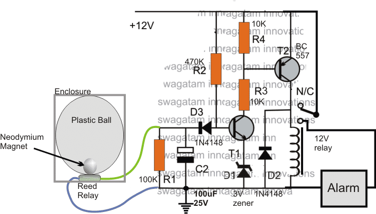
A simple motorcycle accident alarm circuit can be built at home with the help of the design shown in the above figure.

The circuit is made up of two stages, the tilt sensor, and the delay ON alarm stage.

The sensor can be seen at the left side of the design, consisting of a plastic ball, a small spherical neodymium magnet and a reed switch.

The magnet is inserted into the plastic through a temporary hole made at the top, which is later on sealed with epoxy glue.

On the outer side of the ball, a reed relay switch is glued such that the magnet and the reed lie side by side with only the ball plastic separating them.

The above situation is supposed to keep the reed relay switched ON as long as the ball is not tilted and the magnet inside is vertically still in the shown specified position.

The reed relay output can be seen integrated with a delay On relay timer circuit comprising a couple of BJTs and the associated resistors and capacitors.

In the normal situations, while the reed relay is in the activated position, the base of T1 is held grounded and the delay ON timer is unable to react, and remains in a dormant condition.

The sensor unit along with the circuit is supposed to be fixed in the bike such that as long as the bike is in its vertically standing position, the magnet maintains its position around the bottom center of the ball.

However in an event of an accident, when the motorcycle could be in a tilted situation the magnet would roll and be displaced from the specified position allowing the reed switch to open.

As soon as the reed relay opens, C2 begins charging and the delay circuit begins counting.

Depending on the values of C2 and R2 (which could be set for 5 seconds delay), C2 charges fully and triggers T1 into conduction.

This in turn switches ON T2 and the relay, sounding the alarm, and informing the people around regarding the mishap.

The alarm is stopped as soon as the motorcycle is lifted on its upright position or the battery power is disconnected.


You'll also like:

  • 1.  Customizing Car Side Marker Lights to Flashing Side Markers
  • 2.  Motorcycle Button Start Locking Circuit
  • 3.  Car Turn Signal Flasher Circuit with Lamp Malfunction Indicator
  • 4.  Police/Ambulance Siren Circuit with Rotating Beacon Light
  • 5.  Darkness Activated Car Head Lamp Circuit with DRL
  • 6.  Car Blown Brake Light Indicator Circuit to Detect Broken Bulb Filament Tail Light

About Swagatam

I am an electronics engineer with over 15 years of hands-on experience. I am passionate about inventing, designing electronic circuits and PCBs, and helping hobbyists bring their projects to life. That is why I founded homemade-circuits.com, a website where I share innovative circuit ideas and tutorials. Have a circuit related question? Leave a comment.... I guarantee a reply!

Previous Post: « LM35 Pinout, Datasheet, Application Circuit
Next Post: How to Make Arduino on Breadboard – Step by Step Instructions »

Reader Interactions

Comments

  1. meet v says

    April 1, 2016 at 7:38 pm

    Hello Swagatam
    I want to make torch using two 18650 Li-ion battery and two 1watt LED, can you give me circuit diagram for this project.
    Should I use heat sink for led?
    And 18650 lithium batteries can be charged with 1 amp. cellphone charger?

    Reply
    • Swagatam says

      April 2, 2016 at 4:24 am

      hello meet,

      you can connect the two LEDs in parallel and directly with the battery.

      yes the LED will require a good heatsinking

      the battery can be charged with 1amp charger.

      Reply

Need Help? Please Leave a Comment! We value your input—Kindly keep it relevant to the above topic! Cancel reply

Your email address will not be published. Required fields are marked *

Primary Sidebar

Subscribe to New Circuit Ideas

Categories

  • Arduino Projects (87)
  • Audio and Amplifier Projects (132)
  • Automation Projects (17)
  • Automobile Electronics (101)
  • Battery Charger Circuits (83)
  • Datasheets and Components (104)
  • Electronics Theory (143)
  • Free Energy (37)
  • Games and Sports Projects (11)
  • Grid and 3-Phase (19)
  • Health related Projects (25)
  • Home Electrical Circuits (12)
  • Indicator Circuits (14)
  • Inverter Circuits (87)
  • Lamps and Lights (142)
  • Meters and Testers (69)
  • Mini Projects (46)
  • Motor Controller (64)
  • Oscillator Circuits (27)
  • Pets and Pests (15)
  • Power Supply Circuits (108)
  • Remote Control Circuits (50)
  • Security and Alarm (64)
  • Sensors and Detectors (101)
  • Solar Controller Circuits (59)
  • Temperature Controllers (42)
  • Timer and Delay Relay (49)
  • Transmitter Circuits (29)
  • Voltage Control and Protection (37)
  • Water Controller (36)

Calculators

  • Battery Back up Time Calculator
  • Capacitance Reactance Calculator
  • IC 555 Astable Calculator
  • IC 555 Monostable Calculator
  • Inductance Calculator
  • LC Resonance Calculator
  • LM317, LM338, LM396 Calculator
  • Ohm’s Law Calculator
  • Phase Angle Phase Shift Calculator
  • Power Factor (PF) Calculator
  • Reactance Calculator
  • Transistor Astable Calculator
  • Transistor base Resistor Calculator
  • Voltage Divider Calculator
  • Wire Current Calculator
  • Zener Diode Calculator
  • Filter Capacitor Calculator
  • Buck Converter Calculator
  • Boost Converter Calculator
  • Solar Panel, Inverter, Battery Calculator
  • Wire Current Calculator
  • SMPS Transformer Calculator
  • IC SG3525, SG3524 Calculator
  • Inverter LC Filter Calculator

People Also Search

555 Circuits | 741 Circuits | LM324 Circuits | LM338 Circuits | 4017 Circuits | Ultrasonic Projects | SMPS Projects | Christmas Projects | MOSFETs | Radio Circuits | Laser Circuits | PIR Projects |

Recent Comments

  • Swagatam on How Shunt Regulator TL431 Works, Datasheet, Application
  • SA on How Shunt Regulator TL431 Works, Datasheet, Application
  • Swagatam on Battery Deep Discharge Protection Circuit
  • Swagatam on 10 LED Tachometer Circuit Diagram
  • Drew Adare on How to Collect Free Energy from Atmosphere

Company

  • Privacy Policy
  • Cookie Policy
  • About Me
  • Contact
  • Disclaimer
  • Copyright
  • Videos
  • Sitemap

Social Profiles

  • Twitter
  • YouTube
  • Instagram
  • Pinterest
  • My Facebook-Page
  • Quora
  • Stack Exchange
  • Linkedin
  • © 2025 · Swagatam Innovations