In this post I have explained how to apply the IC L6565 for making a compact multi purpose 110V, 14V, 5V SMPS circuit using minimum number of external components.
Implementing quasi-resonant ZVS flyback
The IC L6565 from ST Microelectronics is designed as a current-mode primary controller chip, to specifically suit quasi-resonant ZVS flyback converter applications. The quasi-resonant implementation is accomplished through demagnetization of a transformer sensing input, which is used for switching ON an attached power mosfet.
During the operations of this IC in a converter, the variations in the power capacity of the converter becomes compensated by a line feed forward stage acquired through the line voltage.
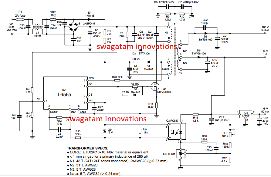
Circuit Diagram
Whenever the connected load is minimal or absent, the IC displays a unique feature which automatically brings down the operating frequency of the converter, and yet ensuring the operation at as far as possible around the ZVS level.
Converters using IC L6565 not only enables low consumption of the design through a low start up current, and a sustained low quiescent current, the system makes sure that it perfectly complies with Blue Angel and Energy Star SMPS guidelines.
In addition to the above explained features, the chip also includes an configurable auto disable function, an in-built current sense and shut down function, and also an accurate reference voltage input for executing basic regulation functions, and an ideal two stage overload protection.
How this 110V/14V/5V SMPS works:
In quasi-resonant SMPS circuits, the operation is implemented by synchronizing the mosfet's switch ON frequency with the demagnetization frequency of the transformer, which is generally accomplished by sensing the falling edge or the negative edge of the transformer's relevant winding voltage.
The above procedure is very simply executed by the IC L6565 through an exclusively designated pinout and using just a single resistor.
This operation enables the voltage, current variable frequency operation feature (in response to a varying input voltage current situations).
The circuit is designed to run approximately within the DCM (Discontinuous Conduction Mode) and CCM (Continuous Conduction Mode) operational mode of the transformer, which can be compared quite like a ringing self-oscillating choke converter or RCC converter.
The pin#8 which is the Vcc of the IC acquires an operating supply voltage from an external regulator network, which sets a 7V rail internally, and this voltage helps to run the entire functionality of the IC and for all the specified executions, associated with its remaining pinouts.
The IC includes an in-built bandgap circuit which enables the generation of an accurate 2.5V reference voltage for ensuring an improved regulation to the control loop used with primary feedback functionality.
You will also find an under-voltage lockout or UVLO comparator with hysteresis featured in the design, which allows the chip to shut down in case the Vcc drops below a specified voltage limit.
A zero current detection stage which is integrated within the IC becomes responsible or switching the external power mosfet in response to every negative edged pulse below the 1.6V level that's fed to this relevant pinout marked as ZCD (pin#5).
However keeping the noise immunity factor in mind and to control it effectively, the associated triggering block must get activated before pin#5 is allowed to fall below 1.6V, by enabling a +2.1V on this pinout.
This process helps the detection of the transformer demagnetization required for the quasi-resonanat operation, in which the transformer's auxiliary winding provides the required signal to the ZCD input, in addition to the IC supply.
In an alternate method where the mosfets may be intended to run in the PWM mode rather than quasi-resonanat mode, the above process can be employed for synchronizing the mosfet switch ON in response to negative pulses from an external source.
Shut Down Option
In such cases the triggering block is forced to go through momentary shut down as soon as the mosfet is switched OFF. This helps to achive a couple of objectives:
1) To ensure that the negative edged pulses following the leakage inductance demagnetization does not accidentally triggers the ZCD circuit stage, and
2) To acknowledge the functioning termed as frequency foldback.
To initiate the external mosfet at the start up, an internal starter stages i used, which enable the driver stage to execute a triggering pulse to the mosfet gate, this becomes necessary due to the absence of an initializing signal to the mosfet from the ZCD pin.
In order to keep the external component to minimum associated with auxiliary winding or a possible external clock, the voltage at the ZCD pin is enabled with a double clamping.
The upper clamp voltage is fixed at 5.2V while the lower clamping potential is rendered at one VBE over the ground level.
This enable the interface to be configured using a just one external resistor for limiting the sourced current which is furthermore shunted by the relevant pinout as per the specified values set for the internal clamping voltages.
For more info regarding the additional internal stages of this 110V, 14V and 5V rated SMPS circuit, you can refer to the original datasheet of L6565

Questions & Answers
Hi Mr. Swagatam;
My SMPS output is 84V DC 8A. Output capacitor is also 100V 470uF and there was a resistor about 10K ( may be 2 or 5 W it is absent at the moment) between this capacitor legs (parallel mounted). Is that resistor is for discharging safety purposes or not?
Can I use the smps without this resistor?
Hi Suat,
Yes that resistor could be for discharging the stored voltage inside the capacitor, and it may be also working as a dummy load to ensure proper initialization of the SMPS, so according to me it should not be removed.
Thanks for the reply. As it can be assumed this SMPS is for battery charging. Is it possible to calculate exact value of the resistor since it is already removed before or 10K resistor may meet the necessity?
I think calculation is not required because the value is not critical, so 10k should be OK.
Hi Mr. Swagatam;
I would like to make my own smps circuit (input 220 output 110 AC 8A) and use pic programme to control the frequence of the smps transformer. But I am not sure about that what kind of transformer I should use. Is it possible to use the one removed from the 84V DC battery charger?
Hi Suat,
An SMPS transformer will always need to be calculated, because its winding configuration will be different for different SMPS specifications. So I don’t think the 84V transformer can be used in your design.
Hi Mr. Swagatam;
Ref. to above circuit I think PC187 is used to sending feedback about output voltage to the L6565 via its pin4. Its voltage waveform to L6565 is linear or square or etc?
Hi Suat, yes it is a feedback control to keep the output voltages stabilized.
The response will be rapid in pulsed form, depending on the value of C9….
Hi Mr Swagatam;
My smps transformer input is 220V AC and output about 83V DC.
Is it possible to apply about 25V AC to the input and gain about 9V DC at the output or that may be defective for the circuit?
Hi Suat,
I don’t think that will work, because SMPS transformers are designed to work with calculated voltages and frequencies, which cannot be changed significantly.
Hi Mr Swagatam;
My charger circuit smps transformer pins detail are as follows;
Primary side:
Pins 1, 2 and DC 318V are connected together.
Pins 5, 6 and mosfet drain pin are connected together.
I think pin 3 and 4 are auxiliaries. And Pin 4 for the driver IC feeding.
Secondary side:
pins 1, 2, 3 and 82V capacitor (-) pole are connected together.
pins 4, 5, 6 and fast diode pin are connected together.
Pin 7 goes to 16V capacitor (+) pole.
Pin 8 is also both connected (-) pole and pin 3 of the primary side with a capacitor as isolated.
It is possible to test the transformer by injecting low voltage and how much voltage should be applied?
Hi Suat,
The primary side of an SMPS works with 220V or 120V AC, so it can be very difficult to use mains AC voltage and test the SMPS transformer by trial and error, it can be very dangerous to do this. Moreover, SMPS transformers are ferrite cire transformers which require accurately adjusted frequencies and pWm for operating correctly, how can we achieve that?.
Thanks for the detailed response. I am sorry, I just try to understand my transformer is defective or not. I do not need to test its performance.
OK, in that case you can add a frequency input and test the transformer winding response. It might help you to understand whether your transformer is OK or not.
Dear Sir, can you please advice necessary changes in the above circuit to adjust current between 0~5Amp for the 105V output? Thanks in anticipation.
Hi Imsa,
You can try using more number of wire strands in parallel for the winding. This might help you to get more current from the same transformer.
Dear Swagatam, I need some guidance on an SMPS used on a portable fridge. It uses the L6598 offline SMPS controller. Input voltage is 230VAC and the expected output voltage is 12VDC. I have changed the Ic with a new Ic, but the output remains on 50% voltage – 6,2VDC. All the discrete components measure fine. I am asking for some guidance on where the problem might be. It has an optocoupler for feedback to the Rfmin pin4. I have changed all the capacitors on the board. I am not sure what the waveforms should be on the HVG, LVG, and OUTPUT pins. The controller is a SECOP 101N0500 for a Danfoss 12/24VDC compressor. I can’t find any dedicated circuit diagram for this controller. The 12VDC battery input side is working perfectly. Thank you. Your assistance will be highly appreciated.
Dear Hennie, as you mentioned about the opto coupler feedback, SMPS circuits normally include an opto coupler feedback circuit which regulates the output voltage of the SMPS. This opto coupler will additionally have a few associated components like a zener diode or a potential divider resistors. These parts normally along with the opto coupler decide the output voltage of the SMPS. You can probably try tweaking the values or settings of these parts to see if that helps to alter the output voltage. An example design can be seen below for reference:
Hi Swagatam, thank you for the prompt response. I will scrutinize the board for the relevant components to determine where the fault lies.
I appreciate your assistance.
Hennie
You are welcome Hennie! All the best to you!
Very useful information you have posted!, could this SMPS work on 220v?, what would i need to change?
Thank you, yes the smps can work with inputs from 85V to 285V AC
hi,
do you provide the material also for these projects?
sorry I don’t provide the materials…
hi sir, i am searching a power supply whose input is 220vac and two different outputs, one is 9 vdc and other is 12v dc . can you help me for this ckt. i found this type of supply in most of the beauty parlor machines. help me for this type of supply making.
Hi Tularam, just buy a 12 V SMPS, and add a 7809 IC at its output, this will allow you to access 12v and 9V both from the same power supply.
I want to convert 24vdc to 110vdc 3Amp can do it with this circuit i want to drive a 2 amp coil from 24vdc battery .
You will need an inverter circuit for this, not the SMPS shown above.
Can i use tl494?