A very simple 10 LED roulette wheel circuit is shown here. pressing the button starts the LEDs in a rotational motion (sequencing) at full swing initially, and gradually slows down, until it stops to a particular, randomly selected LED.
The randomness of the selection depends upon the time for which the push remains switched ON by the finger.
Even a difference of 0.1 second is able to change the position of the final LED position, making the roulette application highly foolproof.
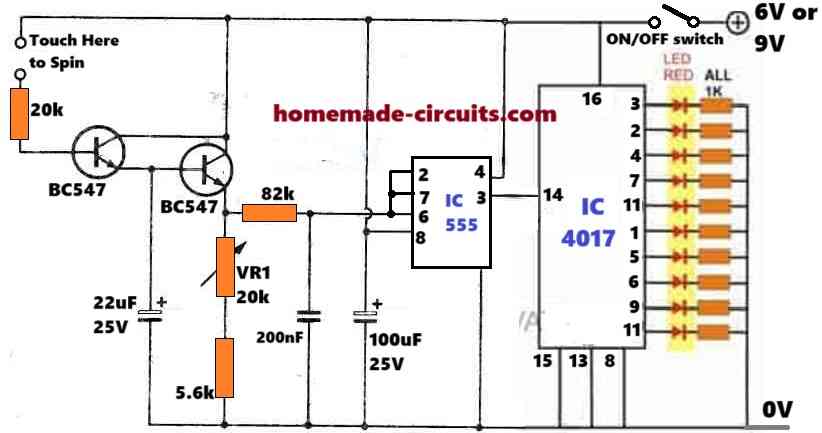
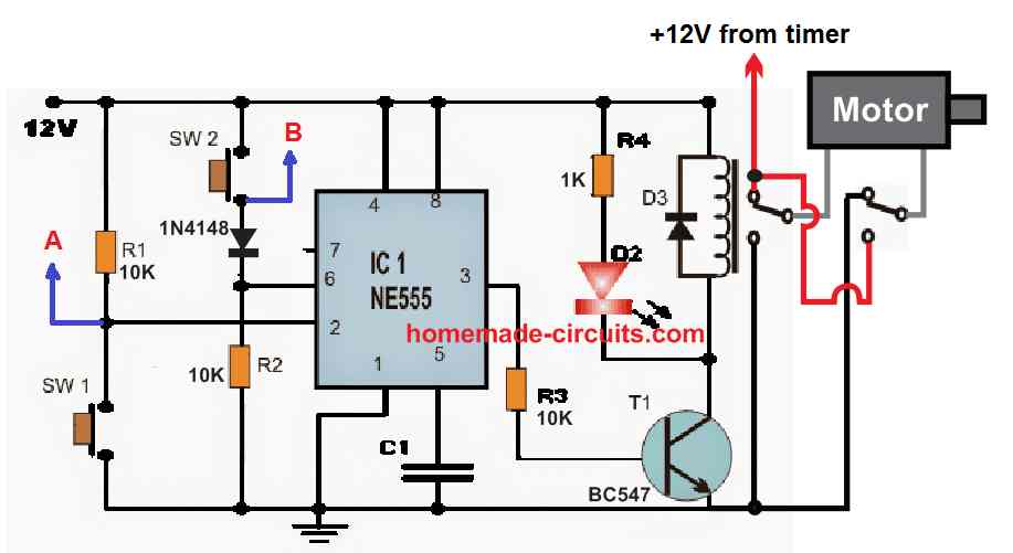
10 LED Simple Roulette Wheel Circuit Diagram

Analysis of the Touch-Spin LED Roulette Circuit
This circuit has the following features:
A touch-spin switch to communicate with the user.
clock pulses produced by a NE555 timer integrated circuit.
The LEDs are sequenced using a CD4017 decade counter.
Transistors BC108 are used to power the LEDs.
The LEDs simulate a roulette wheel by lighting up in a circle in succession.
Main Components and Formulas:
Clock Generator (NE555 Timer in Astable Mode):
To provide the CD4017 counter with a steady clock signal the NE555 is set up in astable mode.
Frequency Formula:
f = 1.44 / ((R1 + 2 * VR1) * C)Where:
f= Clock frequency (Hz)R1= Fixed resistor (5.6kΩ)VR1= Adjustable resistor (20kΩ)C= Timing capacitor (200nF)
For example if we assume VR1 is set to 10kΩ:
f = 1.44 / ((5.6k + 2 * 10k) * 200nF)
  = 1.44 / (25.6k * 200nF)
  = 1.44 / 0.00512
  = 281.25Hz
You can adjust VR1 to change the frequency which alters the LED switching speed.
CD4017 Decade Counter:
The NE555 sends clock pulses to the CD4017 which progressively activates each output one at a time. After the tenth output the sequence is reset.
Clock Input:
The clock signal from the NE555 decides how much speed at which the LEDs switches.
LED Driver Transistors (BC108):
The BC108 transistors amplify the current to drive the LEDs.
Base Resistor Calculation: The resistor connected to the base of each transistor ensures proper biasing.
Formula:
Rb = (Vclock - VBE) / IBWhere:
Vclock= Clock signal voltage (~5V)VBE= Base-emitter voltage (~0.7V for BC108)IB= Base current, calculated asIC / hFEIC= LED current (20mA)hFE= DC current gain (~200 for BC108)
For a 20mA LED current:
IB = IC / hFE
   = 20mA / 200
   = 0.1mA

Rb = (5 - 0.7) / 0.1mA
   = 4.3 / 0.0001
   = 43kΩ
LED Current Limiting Resistors:
Each LED will require a resistor to limit its current and prevent damage.
Formula:
RLED = (VCC - VF) / IFWhere:
VCC= Supply voltage (6V)VF= LED forward voltage (~2V for red LEDs)IF= LED current (20mA)
RLED = (6 - 2) / 20mA
     = 4 / 0.02
     = 200Ω
In the circuit 100Ω resistors are used, which allows slightly higher current for brighter LEDs.
Capacitor Selection (Smoothing and Timing):
- 25µF Capacitor: Filters noise at the spin switch input.
- 200nF Capacitor: Determines the NE555 clock frequency.
- 100µF Capacitor: Stabilizes the NE555 operation and smooths power supply fluctuations.
Adjustable Timing:
The NE555 frequency can be adjusted via the VR1 potentiometer, giving you control over how quickly the roulette "spins." The LED transitions are slowed down by increasing VR1 which lowers the frequency.
Operation:
The NE555 timer begins when the user presses the "SPIN" button which causes the BC108 transistors to amplify the signal.
VR1 determines the frequency at which the NE555 produces a clock signal.
Each LED is lit sequentially by the CD4017 decade counter-stepping via its outputs.
When the touch input is removed the sequence is slowed down until just one LED is illuminated simulating the roulette halting.
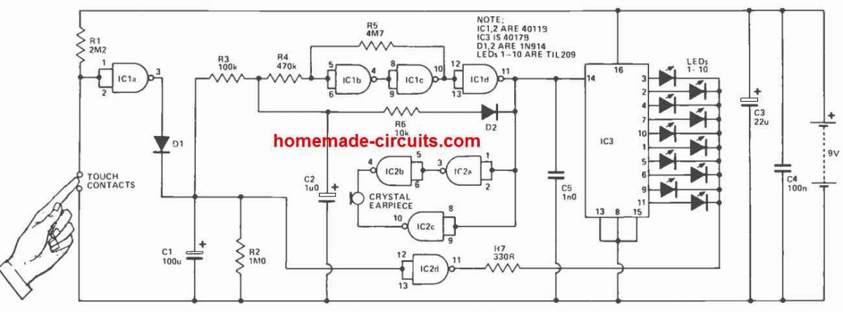
Wheel of Fortune
Parts List
| Component | Value/Description | Type |
|---|---|---|
| Resistors | ||
| R1 | 2.2MΩ (¼W, 10%) | Resistor |
| R2 | 1MΩ (¼W, 10%) | Resistor |
| R3 | 100kΩ (¼W, 10%) | Resistor |
| R4 | 470kΩ (¼W, 10%) | Resistor |
| R5 | 4.7MΩ (¼W, 10%) | Resistor |
| R6 | 10kΩ (¼W, 10%) | Resistor |
| R7 | 330Ω (¼W, 10%) | Resistor |
| Capacitors | ||
| C1 | 100µF, 10V (Tantalum) | Capacitor |
| C2 | 1µF, 10V (Tantalum) | Capacitor |
| C3 | 22µF, 10V (Tantalum) | Capacitor |
| C4 | 100nF (Polyester) | Capacitor |
| C5 | 1nF (Polyester) | Capacitor |
| Semiconductors | ||
| IC1, IC2 | 4011B | Integrated Circuit |
| IC3 | 4017B | Integrated Circuit |
| D1, D2 | 1N914 | Diode |
| LED1–10 | TIL209 | LED |
| Miscellaneous | ||
| - | Battery | Power Source |
| - | Crystal Earpiece | Accessory |
| - | Drawing Pins | Hardware |
| - | Vero Box | Enclosure |
| - | PCB | Circuit Pattern |
The Wheel of Fortune circuit could be categorized into a range of specific stages; the LED display stage, an wheel sound audio stage, a voltage controlled oscillator, and a touch sensitive/monostable circuit.
While in the switched "off' condition resistor R1 maintains the IC1a input high and therefore the output of this gate, rigged like an inverter, stays low and C1 is discharged.
Connecting the touch pads allows the gate's output to turn high and causes C1 to charge up through D1.
As soon as the finger is taken off from the touch pads and the IC1a output becomes low again, C1 is prohibited from discharging into this gate as D1 now gets reverse biased, rather C1 discharges gradually through R2. The VCO is created through the elements involved with IC1b, c and d.
This wheel of fortune circuit actually produces a number of negative pulses with fixed time period split up by "gaps" whose length of time could be chnaged through the control voltage.
As soon as the control voltage (the voltage across capacitor C1) goes under a given limit which is of about 1 / 2 supply voltage the circuit stops oscillating.
In case if it is assumed that the voltage across capacitor C1 goes up to the supply voltage level, which could happen once the touch pads are contacted with the finger, capacitor C2 will begin to slowly charge.
The C2 voltage is provided by means of R4, to the schmitt trigger created by IC1a and b.
As the voltage delivered across the schmitt passes across its top switching limit, the IC1d output, which is responsible for inverting and buffering the schmitt's output, turns low.
This forces capacitor C2 to start discharging very fast through the fairly low impedance route provided by R6 and D2.
As the voltage across capacitor C2 falls below the lower limit of the schmitt IC1d output turns high again allowing C2 to resume charging yet again.
The time consumed for C2 voltage to get to the schmitt's trigger level relies upon the voltage across C1.
Therefore once the voltage across the capacitor C1 become large enough, causes capacitor C2 to swiftly reach the activation stage and the VCO begins generating a high frequency.
This frequency goes on becoming less and less as the voltage across C1 slowly drops.
The output voltage generated from the VCO is delivered to both IC3 to operate the connected LED ring and also to IC2a, b and c to generate the "tick-tick" audio output, imitating the roulette wheel rotation sound.
The crystal earpiece which is used for producing the "clicking" sound is operated through a bridge circuit.
This successfully causes voltage applied to the transducer to become twice in value and as a result, using the formula P = V^2/R, helps to create a louder audio output.
The LEDs are operated by IC3 whose cathodes can be seen hooked up by means of R7, to the IC2d output.
The output of this gate normally stays high, and turns low only when the voltage across the capacitor C1 goes over the half supply threshold.
With the IC3 outputs in the active high position, the wheel of fortune LED display is as a result gets enabled for a time slot that is a little bit extended compared to the time duration of the VCO's oscillation frequency.
Capacitors C3 and C4 are incorporated to enable the decoupling of the supply voltage, and capacitor C5 is included to protect against any RF disturbance that may affect the circuit's functioning adversely.
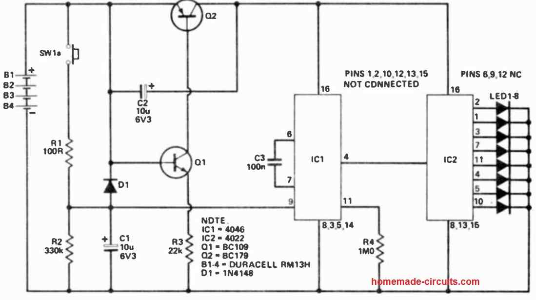
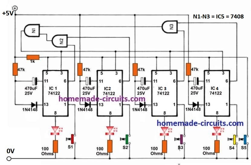
Simplest 8 LED Roulette Wheel Circuit
The working details can be understood through the following explanation:
IC2 functions as a Johnson counter, sequentially illuminating the LEDs upon each clock pulse.
The clock signal is generated from the VCO segment of a phase-locked loop, namely IC1.
The frequency produced by IC1 is determined by the voltage applied to pin 9.
Upon pressing the spin button, capacitor C1 charges close to the positive supply voltage through resistor R1.
Following the release of the button, the charge gradually dissipates over several seconds via resistor R2.
Consequently, this results in a swift rotation of light around the LED circle while the button is held down.
Once the button is released, the rotation slows progressively until coming to a complete stop.
Transistors Q1 and Q2 play a role in disconnecting the power supply when the casino is inactive.
When the spin button is pushed, Q1 draws current through resistor R3, turning on Q2 and enabling the circuit's operation.
Releasing the button raises the negative terminal of capacitor C2 to nearly the full supply voltage. C2 experiences gradual charging due to the base current supplied to Q1, which in turn reduces the voltage across R3.
After a minute or so, Q1's ability to draw sufficient current diminishes, causing Q2 to lose its strong conduction.
The collector voltage of Q2 slightly drops, leading to a decrease in Q1's base voltage and subsequently lowering the current flow from Q1.
This regenerative process promptly cuts off the current, putting the casino in a standby mode where only Q2's leakage current is drawn until the spin button is pressed once more.
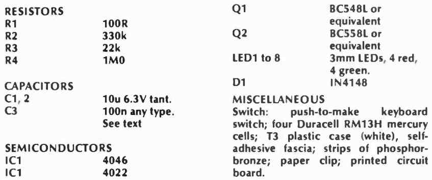
Parts List


Questions & Answers
Hello Swag,
I hope you’re doing well.
Regarding your “10 LED Simple Roulette Wheel Circuit Diagram”, is there a way to reduce the LED’s from 10 to 5, yet still have a running loop from 1 -5 random lights?
Also, is there a way to reduce the looping wait time down to just a few seconds?
Many thanks!
Paul DeMichael
Also,
Perfect, thanks so much Swag!
Thanks Paul,
Yes, it is possible… simply by disconnecting pin#15 from the ground, and connecting to the 4017 output pin which comes just after the last LED count, which is in your case is the 5th LED.
The looping delay can be reduced by adjusting the 2200F capacitor value to some lower value…
Sir, I have a similar circuit that I made from Elektor magazine called “Russian Roulette. I think it would be a great addition to your site. It can be found on page 14 in the July/August issue from 1981.
Also, I could use some help, the audio output is very quiet, could you suggest how to make it louder?
Thanks.
Thank you so much Paul,
I saw the link you sent, it looks interesting, in my free time I will try to modify the design and publish it in the above article.
hi, at the 100k resistor why is there a wire connected at the middle of it? thanks in advance
that is the center pin of the preset joined with one of the outer pins.
Hi,
I would love to understand how exactly the NE555 and decade counter CD4017 with all the other components work in this circuit. Thanks you in advace!
Hi, for that you will have to learn how the 4017 pinouts work:
https://www.homemade-circuits.com/how-to-understand-ic-4017-pin-outs/
Could you please make a circuit on car tail and break light controller. Where the tail light (led strip should glow while the car is running when brake applied it should be more brighter.
Hi ,how to make this circuit with 32 leds.can you send circuit diagram for 32 led’s.
Please reply
It is possible to modify the circuit to 32 LED. I will try to update it soon.
It is already posted in the this website, please use the search box to find it!
Pls i need a circuit of power optimizer or power booster to use pressing iron with small tiger generator, or how can i create the circuit
you will have to provide the complete specification and working details of the project, only then I would be able to suggest…
can you pls list down the values of the needed components like the resistors and capacitors because i cant understand clearly, and can i use different values than the given in the photo?
please click the diagram to enlarge and you will be able see the part numbers clearly
Where should I supply – voltage in the circuit?
(+) at the top most rail or line…(-) at the lower most line or rail
Hi can you please do this by using 32 led’s and could you list out the components required for this same product using 32 led’s .
Hi, 32 LEDs will require 4nos of IC 4017, and 1no of IC 4093, and can make the circuit quite large and complex.
How much supply voltage should be given to it and how can I increase the LED
you can use any supply between 6 and 15V….since there are 10 outputs from the IC 4017 therefore only 10 LEds can be driven….