A bicycle horn is normally used in bicycles for generating an amplified alarm sound with a press of a button for alerting anybody getting on the path of the running bicycle.
In this post I have explained the complete construction of an electronic bicycle horn circuit which will resemble a phone musical ringtone sound.
Introduction
The old fashioned mechanical bicycle horns are slowly getting discarded now and the folks are more interested to replace them with the new musical horns imitating well as phone ringtones.
One such project is discussed in this article. The circuit is very easy to build as it incorporates just a couple of active parts and a few other passive parts. The circuit can be operated with 3 volts DC through two penlight AAA size.
Electronic hobbyists who also own a bicycle will love this project.
The proposed idea will help you to get rid of your old mechanical bicycle honk with a brand new loud electronic musical device.
It's a homemade project - another aspect that will amuse the young folks. I have explained the whole procedure here.
Circuit Operation
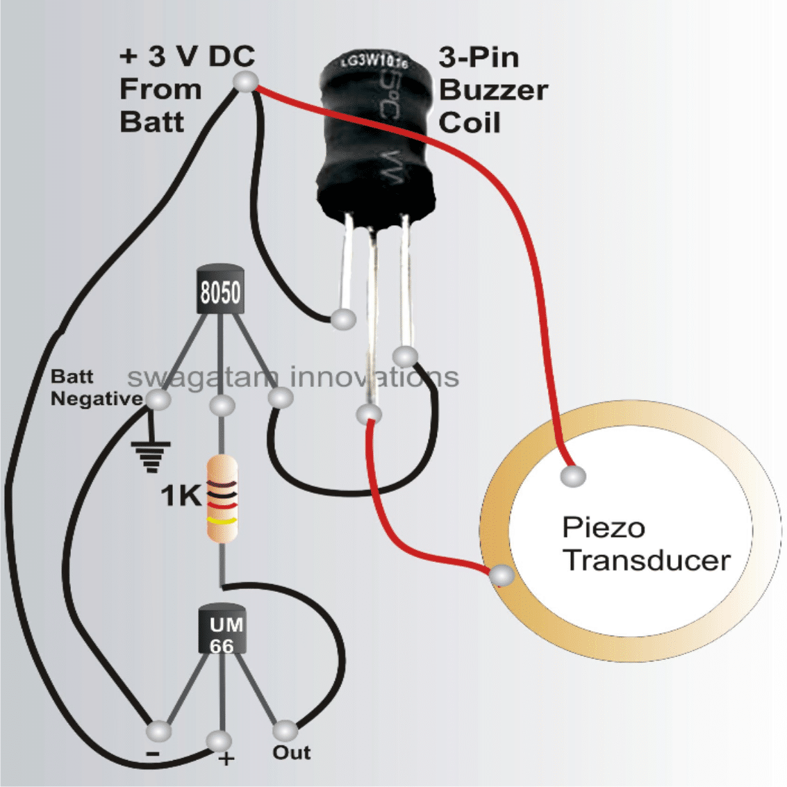
Referring to the above circuit diagram we can see how simple it is to construct the proposed musical hooter as it utilizes very few electronic parts.
The transistor T1 is an ordinary general purpose transistor, the well known 8050. An 8050 is more powerful than the usual BC547 types and is able to handle current up to 150 mA comfortably.
The transistor also owns the property of having greater hFE levels than other similar types of transistor resulting in better amplification of the music, and yes it is there basically to amplify the music source.
The music source here is the incredible IC UM66 which has an embedded piece of music “written” inside it. It just needs a supply voltage of 3 V (not to exceed) to get going. The pin-outs are also pretty simple to understand.
The left one is the negative, center one is the positive and the right leg is the output – simple isn’t that?
Once the relevant supply terminals of the UM66 are assigned to their posts, it starts “singing” right away through its output pin.
However, this audio level is very low and needs to be amplified before feeding it to the step-up coil. This is done by T1 as explained above and the amplified signal is sent to the coil.
Booster Coil
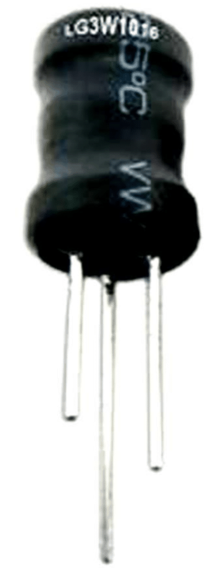
How the Buzzer Coil Works
The coil used here actually acts as a step-up transformer and is primarily used for stepping up the amplified music fluctuations from the transistor T1.
The coil just like any other transformer as a primary and a secondary sections, however the sections are not isolated, rather are wound as a single winding with the center tap appropriately pulled out at the relevant calculated step.
The primary and the secondary winding leads are identified by measuring the corresponding resistances using a multi-tester.
The leads which show lower resistance is the primary winding, and the one which shows relatively higher value is the secondary winding.
Normally the primary section will indicate a value of around 22 ohms while the secondary shows a value of around 160 ohms. The common lead across the measurements is the center tap and goes to the positive supply.
How the Piezo Transducer Works
The piezo plate which is responsible for the actual reproduction of the sound is connected across the secondary winding directly.
The terminals of the piezo from the central white area and the outer metal rim, both the areas are solderable, however soldering the connection over the inner circle needs great care.
Make sure the solder tip is lifted as soon as the solder spot is made, otherwise the white ceramic coating will immediately get burnt reducing some efficiency of the device.
How to Install the Piezo Transducer
Another aspect with the piezo element is its installation or the fixing method.
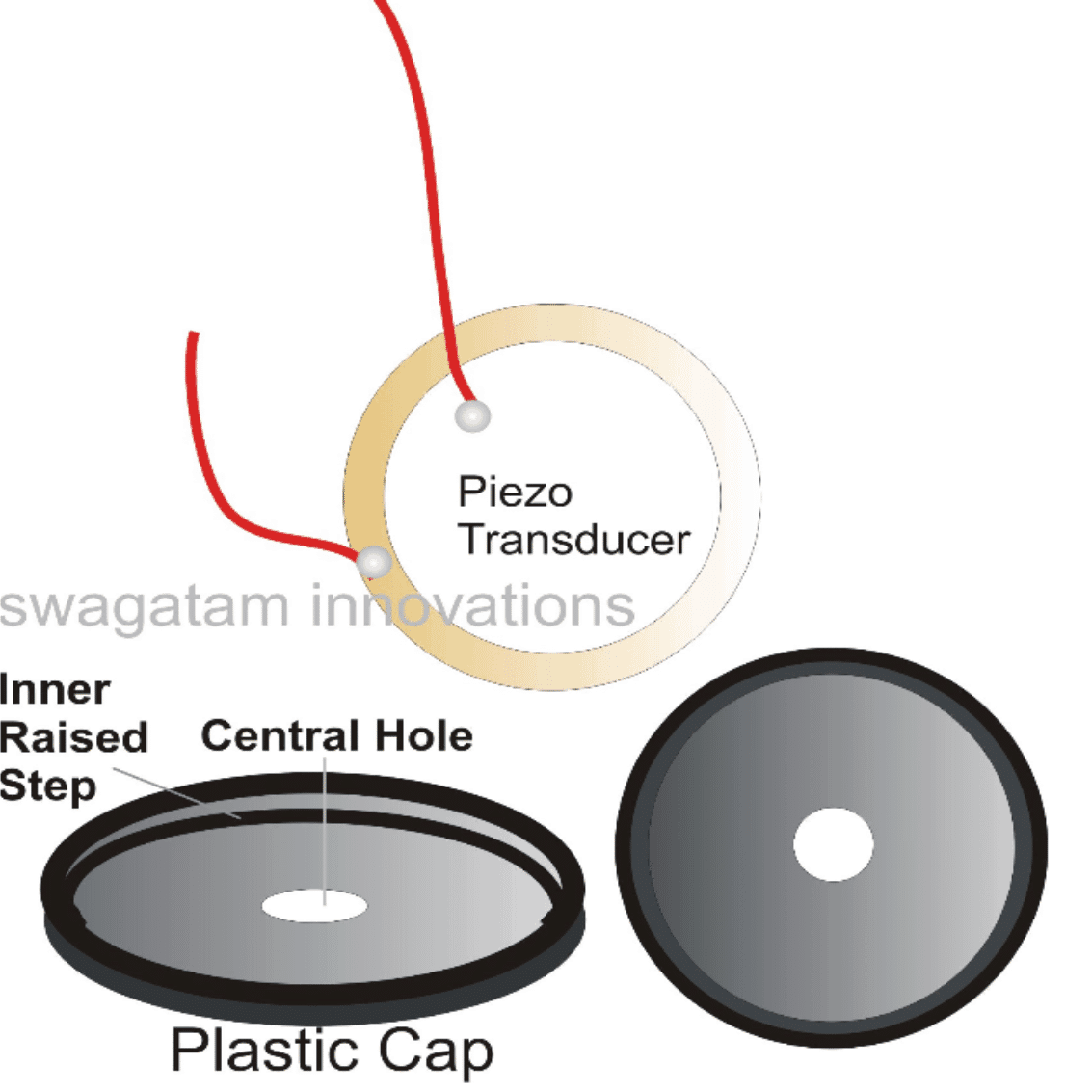
The fixing is done over a plastic dish or cap having some depth (around 5 mm) and an inner elevated step of about 1.5 mm in height and 1 mm in width, covering the inner bottom edge of the cap (see fig).
The inner diameter of the cap is such that the piezo just brushes inside the cap and settles over the elevated step. And it’s exactly how the piezo is placed and stuck inside the cap (see figure).
The sticking can be done by some good quality synthetic rubber based glue (as used for sticking rubber and leathers).
The opposite surface of the cap has a central hole of some calculated diameter (say around 7 mm) and it determines the loudness of the generated sound from the piezo element.
Varying this diameter of the hole can drastically vary the amplification and sharpness of the music intensity.
Once the entire wiring of the circuit and piezo assembly id completed, the unit can be powered using two penlight cells, which gives the required 3 volts to the circuit.
Amazingly even with such low power supply the music intensity can be found to be significantly loud and ear piercing.
Using 3V for the Musical Chip
However the supply must not be exceeded this value because the IC UM66 cannot tolerate anything above 3 volts.
Of course the unit can be used with higher supply voltages, up to 12 volts only if the supply to the IC is checked and regulated to 3 Volts by a resistor and a zener network.
With 12 volts supply the amplification becomes very high and in fact becomes very compatible with cars for using as musical reverse horns.
Parts List for the Bicycle Horn Circuit
All resistors are ¼ watt, CFR, 5 %, unless otherwise stated
- R1, R2 = 1 K = 1
- T1 = 8050,Coil = As shown in the diagram = 1
- COB = UM 66 IC or any other similar type = 1
- Piezo = 27 mm, two terminal type, as shown in the diagram = 1
- PCB = Veroboard or any general purpose PCB = 1


Questions & Answers
Sir, could you kindly please share the link of the 3 PIN INDUCTOR COIL to purchase it online?
Hi Arun, please Google “3 pin Buzzer coil” you will be able to find many good online sources.
Electronics had been my Prime Hobby since 70s and even while I was doing my Engineering on other Disciplines( VIZ., Civil, Electrical and Mechanical) My Most Favorite Hobby was to fiddle with Electronics only and I ended up building a Motorcycle Horn(Beep-Beep) Tone Generator by altering the values of Capacitors and Resistors of a Basic Morse Code Oscilator`and it became so popular in our Hostel that, I had to build it for many of my friends to be used on their Bicycles and also for using as Calling Bells. But I have lost the Diary where I had Drawn it! Sir, Could you please design a similar circuit to produce a BEEP-BEEP tone by using Transistors or NE555?
Thanks for your interesting feedback. I appreciate it very much.
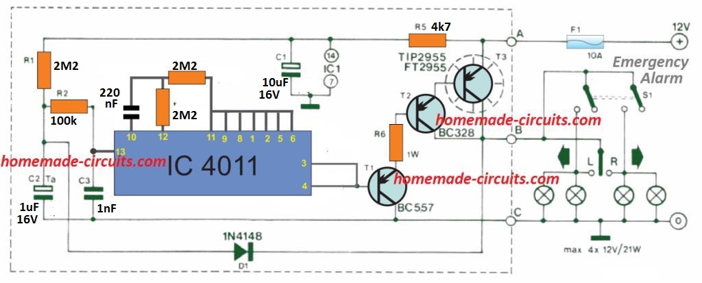
You can perhaps try the following circuit:
The transistor are incorrectly shown as PNP AC128. Please replace them with NPN BC547 transistors.
could the 8050 be replaced by any power transistor to drive a ultra powerful ultrasonic 50watt< transducer? (supplying the circuit/12v)
Yes, that’s possible…you can try TIP142 BJT
Very Nice circuit
I know, I bought Piezo, now I just want to change the music to fire alarm (because I want to design a Mini alarm product with a handbag). For example, does calibration of the capacitor or resistor work? Thank you very much.
Increasing the 1k resistor may reduce the sound level, apart from that there’s no other adjustment.
Hello Swagatam, I want to do a small project, something like your circuit board introduced on the Web site https://www.homemade-circuits.com. How to create a circuit with bicycle horns with ringtones. But here I instead do mini alarm circuit handheld or carry a bag. But I have the desired loud 110dB alarm, using AAA batteries. So I need your help to improve the above schematic design.
Thank you very much.
My name is: Huynh Minh Hoang.
Email: minhhoangtk78@gmail.com
Address: 109 Thanh Thuy, Thanh Binh Ward, Hai Chau District, Da Nang City, Vietnam,
Hello Huynhh, the circuit explained will produce a very loud ear piercing musical sound, if everything is done as per the diagram set up. So yo can go with the design which is explained in the above article, but make sure to stick the piezo exactly as per the given instructions, because the piezon sticking is crucial for getting the most optimal sound output
What is the capacity of the inductor? Why are you using 3 pin inductor instead of 2 pin inductor. How would the circuit change if a 2 pin inductor is used? How would you make a warbler sound instead of using the musical sound of um66 when using an active piezo instead of the passive piezo shown? Thanks!
Inductance of the coil is unknown because this coil is supposed to be purchased not hand made.
3 pin will produce 5 times more volume than a 2 pin.
for 2 pin simply connect the ends across collector of 8050 and supply positive, and connect the piezo parallel with the coil terminals.
hi, I’m From Rajapalayam. I did not find that coil in my town.the image name says it is inductor…if it is inductor. can we make it home..
Hi, making it with hand can be very difficult and inaccurate, because it has more than 2000 turns in it with calculated taps…better to get it ready made, ……you can get it online also…
Can u post the circuit for "How to Make a Melody Maker – Musical Bike Horn Circuit"
I'll try to design it, and let you know soon.