• Skip to main content
  • Skip to primary sidebar

Homemade Circuit Projects

Need circuit help? Post them in the comments! I've answered over 50,000!

Blog | Categories | About | Contact | Calculators-online
You are here: Home / Electronics Theory / Transistor Stray pickup False Triggering Problem

Transistor Stray pickup False Triggering Problem

Last Updated on March 19, 2019 by Swagatam 4 Comments

In this article I have explained how to make any BJT or mosfet based circuit free from stray signal pickup and false triggering by simply attaching a filter resistor or a capacitor across their base/emitter or gate/source terminals. The problem was raised by Mr.Henrik.

Table of Contents
  • Solving a Circuit Problem

Solving a Circuit Problem

I have an issue I don’t understand. please check out the following diagram.

warning message: electricity is dangerous, proceed with caution
Transistor2Bcircuit

If I connect the Base of a PNP transistor through a 10K resistor to ground the LED lite up. If I disconnect the Base from ground the LED light up weakly. I would have expected the LED to be completely off.Can you explain me why this is the case. I have tried with other transistors also.
If I use a NPN transistor to switch a PNP transistor (Darlington) do I need a resistor from the Base of the PNP to Collector of the NPN transistor?
Thank you,Henrik

 The Reason behind the Fault:

The mentioned problem of false transistor triggering while its base was unconnected to a triggering source may be due to stray signal pickup by the transistor base causing the slight illumination on the LED.

Because as we know that when a small current flows through base emitter of a BJT, forces a relatively more stronger current to pass through collector/emitter of the device. Here too the stray signal at the base of the BJT could be forcing the device to trigger albeit fractionally, but enough to cause a faint illumination on the LED.

The Solution:

The problem could be easily remedied by adding a compensating resistor across the base emitter of the BJT, the value could be anything which allows a 1V across the base emitter when the actual trigger is connected with the base. This value could be evaluated using a resistor potential divider network calculation.

Or simply a matching value resistor could be included similar to the existing base resistor value, as done below.

Transistor2Bcircuit 1

Another simple way to eliminate stray pick up while its base was not associated with any form of input logic or trigger is to add a small value capacitor across its base and emitter, which would help the BJT to effectively ground any possible stray input signal and prevent it from causing the device to conduct spuriously.

Transistor2Bcircuit 2

You'll also like:

  • 1.  How to Compare IGBTs with MOSFETs
  • 2.  How to make a Transistor Latch Circuit
  • 3.  Voltage-Divider Bias in BJT Circuits – More Stability without beta Factor
  • 4.  Calculate Battery, Transformer, MOSFET in Inverter
  • 5.  Inductors in AC/DC Circuits Explained
  • 6.  Understanding Pull-Up and Pull-Down Resistors with Diagrams and Formulas

About Swagatam

I am an electronics engineer with over 15 years of hands-on experience. I am passionate about inventing, designing electronic circuits and PCBs, and helping hobbyists bring their projects to life. That is why I founded homemade-circuits.com, a website where I share innovative circuit ideas and tutorials. Have a circuit related question? Leave a comment.... I guarantee a reply!

Previous Post: « 3 phase Solar Submersible Pump Inverter Circuit
Next Post: Controlling LED Strip Light ON/OFF and Brightness with any Remote Control »

Reader Interactions

Comments

  1. Krishen Gopal Kathel says

    July 17, 2024 at 11:26 pm

    please give difference of pull up and pull down resistance and above theory.
    I want theory to prevent false LED indication of
    any circuit diagram. So circuit would be work proper ON and OFF.

    Reply
    • Swagatam says

      July 18, 2024 at 9:04 am

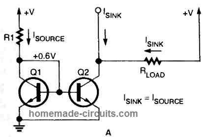
      Pull-up resistor is connected from positive supply to base of a BJT, when the base of this BJT is connected to a sinking source via the collector of another BJT or through a diode from a logic IC output.
      Pull-down resistor is connected between base of the BJT and its emitter supply. It’s basically to add a potential divider network at the BJT base.
      Please provide your LED application details, if possible I will try to solve it for you….

      Reply
  2. Liju says

    March 15, 2019 at 1:00 am

    Can i connect 220v AC line to base of BC546 through a 5M ohm resistor to trigger the transistor ON/OFF.

    The main question is: since the C, E and load is going to b on a DC circuit with a 9V battery, will the domestic line which will not have common ground with this DC circuit trigger the transistor?

    Thanks for your advice in advance

    Reply
    • Swagatam says

      March 15, 2019 at 9:08 am

      You must have the other unused line of the mains connected with the common (-) of the 9V DC otherwise the transistor will not switch. You will have to use a 1N4007 diode in series with the base resistor so that only +DC is able to reach the base.

      5M is too high, you can safely use 100K.

      This design will be non-isolated from mains so extremely dangerous to touch.

      Reply

Need Help? Please Leave a Comment! We value your input—Kindly keep it relevant to the above topic! Cancel reply

Your email address will not be published. Required fields are marked *

Primary Sidebar

Categories

  • Arduino Projects (87)
  • Audio and Amplifier Projects (132)
  • Automation Projects (17)
  • Automobile Electronics (101)
  • Battery Charger Circuits (83)
  • Datasheets and Components (104)
  • Electronics Theory (143)
  • Free Energy (37)
  • Games and Sports Projects (11)
  • Grid and 3-Phase (19)
  • Health related Projects (25)
  • Home Electrical Circuits (12)
  • Indicator Circuits (14)
  • Inverter Circuits (87)
  • Lamps and Lights (142)
  • Meters and Testers (69)
  • Mini Projects (46)
  • Motor Controller (64)
  • Oscillator Circuits (27)
  • Pets and Pests (15)
  • Power Supply Circuits (108)
  • Remote Control Circuits (50)
  • Security and Alarm (64)
  • Sensors and Detectors (101)
  • Solar Controller Circuits (59)
  • Temperature Controllers (42)
  • Timer and Delay Relay (49)
  • Transmitter Circuits (29)
  • Voltage Control and Protection (37)
  • Water Controller (36)

Calculators

  • Battery Back up Time Calculator
  • Capacitance Reactance Calculator
  • IC 555 Astable Calculator
  • IC 555 Monostable Calculator
  • Inductance Calculator
  • LC Resonance Calculator
  • LM317, LM338, LM396 Calculator
  • Ohm’s Law Calculator
  • Phase Angle Phase Shift Calculator
  • Power Factor (PF) Calculator
  • Reactance Calculator
  • Transistor Astable Calculator
  • Transistor base Resistor Calculator
  • Voltage Divider Calculator
  • Wire Current Calculator
  • Zener Diode Calculator
  • Filter Capacitor Calculator
  • Buck Converter Calculator
  • Boost Converter Calculator
  • Solar Panel, Inverter, Battery Calculator
  • Wire Current Calculator
  • SMPS Transformer Calculator
  • IC SG3525, SG3524 Calculator
  • Inverter LC Filter Calculator

People Also Search

555 Circuits | 741 Circuits | LM324 Circuits | LM338 Circuits | 4017 Circuits | Ultrasonic Projects | SMPS Projects | Christmas Projects | MOSFETs | Radio Circuits | Laser Circuits | PIR Projects |

Recent Comments

  • Swagatam on 9 Simple Solar Battery Charger Circuits
  • Swagatam on Arduino Pure Sine Wave Inverter Circuit with Full Program Code
  • Swagatam on How Shunt Regulator TL431 Works, Datasheet, Application
  • Swagatam on Best 3 MPPT Solar Charge Controller Circuits for Efficient Battery Charging
  • Dan Biles on 9 Simple Solar Battery Charger Circuits

Company

  • Privacy Policy
  • Cookie Policy
  • About Me
  • Contact
  • Disclaimer
  • Copyright
  • Videos
  • Sitemap

Social Profiles

  • Twitter
  • YouTube
  • Instagram
  • Pinterest
  • My Facebook-Page
  • Quora
  • Stack Exchange
  • Linkedin
  • © 2025 · Swagatam Innovations