The following experiment shows how interestingly Mr.Steven could draw free energy from air using his home-built sec exciter coil tower, he used it to a feed a small LM317 power supply unit and made it work successfully. Read more...
How to Wind the Inductors
"When i hand wind my coils i didn't use varnish its to soft and takes to long to dry , so i mix a 2 part araldite mix together then use my fingers to apply it while rotating the coil winder by hand so the araldite dries fast and thick and is stronger.
i make my own colloidal silver and soon ill be making the first ever colloidal silver using the same voltage and energy or RF current i get from the sec tower so i hope the energy rf currents and the voltage can make some kind of rejuvenated super water....
ill take some pictures when i get the chance to of all the circuits ive made that are powered from the single output wire of an sec exciter tower including my fast nmh battery charger and high voltage capacitor charger etc etc at first the results of the nickel metal hydride rechargeable battery test was mixed in one test the battery had some voltage left in it and gained a charge up to 12 volts well past the battery's capacity, then another test a battery went flat fast after topping it up using the circuit and
another test the measured battery voltage was going up as if self charging itself , so i wondered if the rf currents and voltage from the sec exciter tower did something to whats inside the battery , its a long story.
Images of Sec Exciter Coil Tower Pototype
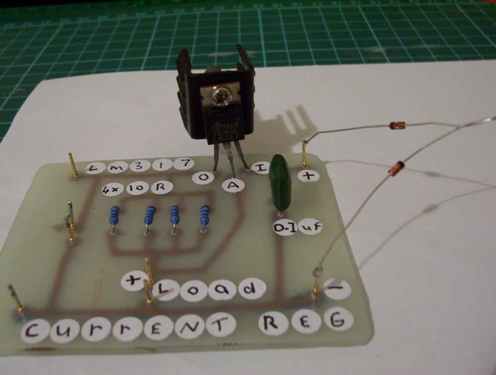
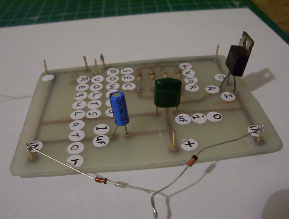
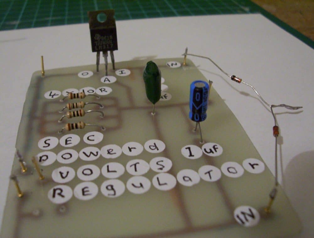
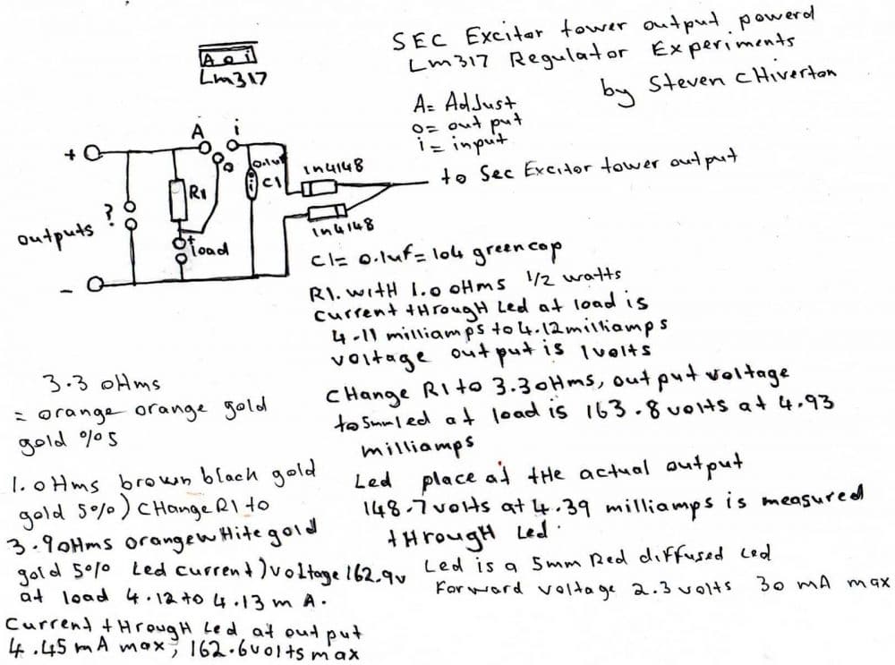
Here are 7 pictures of the sec exciter coil tower powered voltage and current regulator circuits adding just the 2 fremenko plug diodes to these enables them to be powered from a one wire output from the sec exciter coil tower ive got the video of these being tested and its amazing".
Please also see the VIDEO clipping after the images.


Employing a LM317 Circuit
Here's some tests i did with another lm317 regulator circuit i built to
try get the best current and voltage outputs so far it would be suitable to use it to a joule thief to try get a better current output
from it.
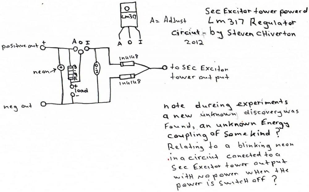
During experiments of my newest sec exciter, tower powered Regulator circuit, I decided to use a spot on the circuit board of my newest Lm317 sec exciter, tower powered regulator circuit,
so I decided to test a neon Out on it so I soldered it into that spot it was marked with a question mark on The other circuit above , the neon light up so there was more than enough Voltage coming out of the output of that circuit to light up the neon.
Illuminating a Wireless Neon Bulb
Then I decided to try another neon at the load area so I Held a neon by one leg and it lit up when I touched the other one leg to the Positive on the load and it even lit up when I touched the neon leg to the Negative of the load , and also when I lit the neon up at the load points the Other neon near the outputs got Brighter .
So I turned the driver Circuit to the sec exciter tower off and I was holding the lm317 regulator by The board and as I touched the negative output pin the neon in the lm317 sec Exciter powered regulator circuit started to flash on and off .
And yet the Power to the driver was off so what the hell was doing this the closest power Source to the circuit was the switched off 9 volts dc 500 milli amps power Supply wire running to the sec driver circuit which was switched off so what the Hell could 9 volts dc at 500 milli amps regulated power supply had to do with The neon flashing on and off its dc regulated so whats the connection.
I pulled the power supply out of the plug to the switched Off circuit and the neon stopped flashing. Now even 9 volts at 500 milli amps is Not enough to flash a neon and the driver circuits power is off and the power Input led is off so wheres the energy, coupling coming from to light the neon.
I did some more testing the sec exciter coil tower powered lm317 voltage regulator circuit and with the neon blinking on and off with the power to the circuit on and the power switch at the circuit in the off position ,
i measured the voltage input into the driver circuit to see if anything was still flowing into it with the power switch in the off position, and measured a tiny 7.0 millivolts through the off switch into the driver circuit , with the amount of parts in the driver circuit and the amount of wire in the sec tower coil it shouldn't off even been able to ignite a neon at all even very dimly on and off like it dose and with 7.0 millivolts input leaking through and the neon blinking on an off continuously while i have my finger grounded to the regulator circuits negative output is a strange one.
The next circuit runs off a one negative wire output of the lm317 circuit that's powered from the one wire output of the sec exciter tower its weird way of operating may be hard to explain for me anyhow so you can see some of what i written down on the drawing , its could end up being the rf version of a new parasite zapper for all i know till i do some more testing 2 of the neons also respond like a body's efeild sensor and lite up when you bring your hands near it


Questions & Answers
about the jpg’s posted on this webpage. the lm317 pin id’s are wrong in the pics, he hand drawing is correct. I thought you should know.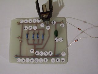
Thank you for notifying…I hope the readers will read this comment and take note of it.
A Hulda Clark zapper pleas