In this post I will show how to construct an interesting Arduino based mini weather station project, which can show you ambient temperature, humidity, pressure, air quality and much more data from your surroundings, which can be used to predict weather from home.
If you are interested in meteorology this project might come in handy for studying about local weather conditions and short term changes. The proposed project is solid state design, which means no moving parts exist.
This project may be placed in indoor or semi-indoor conditions, where the circuit is away from direct sunlight or heavy wind or moisture which can deteriorate the sensors on-board.
The Design:
The proposed mini weather station circuit project is built around Arduino, which is brain of the weather station which does collect lots of data from various sensors and process them and displays on 16x2 LCD screen.
You can choose your favorite arduino board for this project. The circuit consists of three sensors MQ-135, BMP180 and DHT11. Let’s see what each sensor does in detail.
MQ-135 Sensor:
The MQ-135 is air quality measuring sensor, which can detect carbon dioxide, alcohol, benzene, smoke, butane, propane etc.
If the chemical concentration these gases are high in the air, then we can say that air is polluted.
The sensor can detect change in the concentration of pollutants in the air and gives out appropriate voltage level.
The sensor’s output voltage is directly proportional to chemical concentration level in the air.
The voltage variation from sensor is fed to Arduino; we have pre-determined threshold levels in the program.
When it crosses the threshold level the microcontroller tell us whether the air is safe or not.
Circuit Diagram
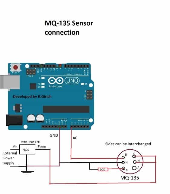
The above diagram shows the wiring diagram. This sensor needs external 5V supply because it has heating element inside the sensor which consumes around 1 Watt.
The power from arduino‘s power pin can’t supply higher current.
The heating element keeps the sensor warm and helps to sample appropriate amount of chemical concentration in air. The sensor takes about couple of minutes to reach optimum temperature.
DHT11 Sensor:
DHT11 sensor is popularly known as Temperature and humidity sensor. It can measure temperature and humidity from surrounding as the name suggests.
It is a 4 pin device but only 3 of them are used. It may look like a very simple component, but it has a microcontroller inside the sensor which passes the data in digital form to the arduino board.
It send 8 bit data every second to arduino, to decode the received signal, we need to include library in the code which is designed to handle it. The link for the library is given later part of the article.
Circuit diagram:
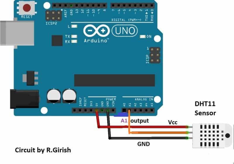
The circuit connection from sensor to arduino is very simple. The output of the sensor is connected to A1 pin of arduino. The supply Vcc and GND are connected to power supply pins of arduino.
Note: Please make sure that your sensor has built in pull-up resistor, if it doesn’t have one; connect a 4.7K pull-up resistor at output pin of the DHT11 sensor.
BMP180 sensor:
The BMP180 is barometric sensor; it can measure atmospheric pressure, altitude and temperature.
The temperature measurement from this sensor is neglected as we have dedicated sensor for measuring the ambient temperature.
The sensor measures altitude of the setup from the sea level, it is also one of the parameter used in meteorology.
Circuit Diagram:
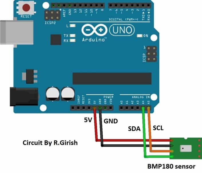
It uses I2C communication protocol, the SDA pin goes to A4 of arduino and SCL goes to A5 of arduino. The Vcc and GND are connected to power supply pins of arduino.
LCD connection:
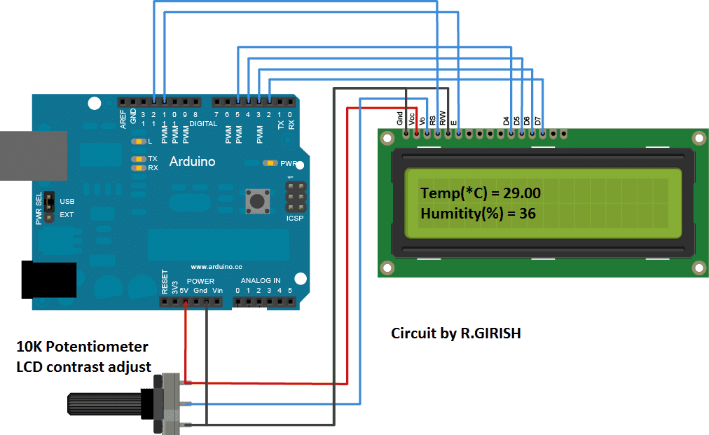
The LCD display shows all the data from the sensors. The connection between LCD display and arduino is standard; we can find similar connection on many other LCD based projects. Adjust the 10K potentiometer for optimum visibility from the LCD display.
Author’s Prototype:
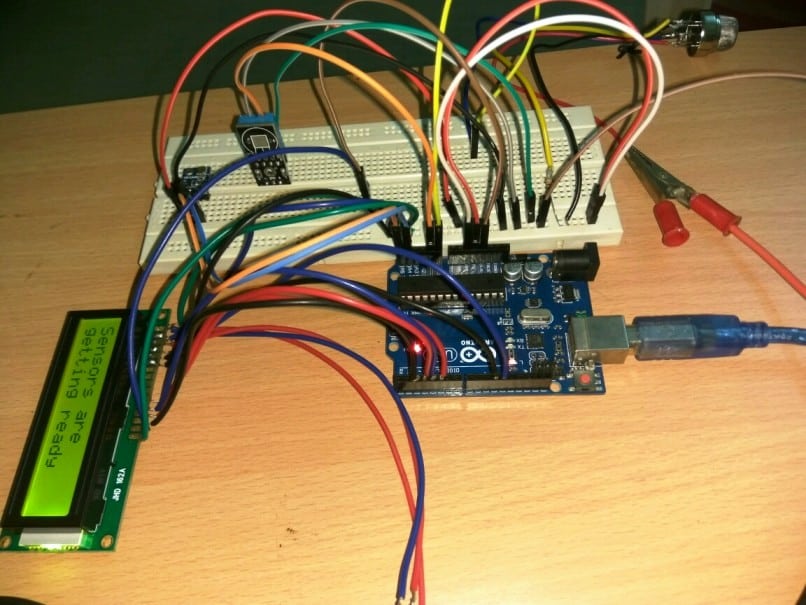
Here is the author’s prototype of a mini weather monitor circuit where all the sensor shown in the schematics are connected to the arduino board.
Note: The circuit connection from each sensors and LCD display should be connected to single arduino board.
We have given discrete sensor connection on each schematic to avoid confusion while duplicating the circuit.
Download the Library files before uploading the code:
DHT11 library: https://arduino-info.wikispaces.com/file/detail/DHT-lib.zip
BMP180 library: github.com/adafruit/Adafruit_BMP085_Unified.git
Program Code:
#include <LiquidCrystal.h>

#include <dht.h>

#include <Wire.h>

#include <Adafruit_BMP085.h>

#define DHTxxPIN A1

LiquidCrystal lcd(12,11,5,4,3,2);

dht DHT;

Adafruit_BMP085 bmp;

int ack;

int input = A0;

unsigned long A = 1000L;

unsigned long B = A * 60;

unsigned long C = B * 2;

int low = 300;

int med = 500;

int high = 700;

int x = 4000;

void setup()

{

Serial.begin(9600);

lcd.begin(16,2);

lcd.setCursor(0,0);

lcd.print("Sensors are");

lcd.setCursor(0,1);

lcd.print("getting ready");

delay(C);

}

void loop()

{

ack=0;

int chk = DHT.read11(DHTxxPIN);

switch (chk)

{

case DHTLIB_ERROR_CONNECT:

ack=1;

break;

}

if(ack==0)

{

lcd.clear();

lcd.setCursor(0,0);

lcd.print("Temp(*C)= ");

lcd.print(DHT.temperature);

lcd.setCursor(0,1);

lcd.print("Humidity(%) = ");

lcd.print(DHT.humidity);

delay(x);

}

if(ack==1)

{

lcd.clear();

lcd.setCursor(0,0);

lcd.print("NO DATA");

lcd.setCursor(0,1);

lcd.print("Check Sensor");

delay(x);

}

if (!bmp.begin())

{

lcd.clear();

lcd.setCursor(0,0);

lcd.print("BMP180 sensor");

lcd.setCursor(0,1);

lcd.print("not found");

while (1) {}

}

lcd.clear();

lcd.setCursor(0,0);

lcd.print("----Pressure----  ");

lcd.setCursor(0,1);

lcd.print(bmp.readPressure());

lcd.print("  Pascal");

delay(x);

lcd.clear();

lcd.setCursor(0,0);

lcd.print("----Altitude----");

lcd.setCursor(0,1);

lcd.print(bmp.readAltitude(101500));

lcd.print("  meter");

delay(x);

lcd.clear();

lcd.setCursor(0,0);

lcd.print("  Air Quality:");

if(analogRead(input)==0)

{

lcd.setCursor(0,1);

lcd.print("  Sensor Error");

delay(x);

}

if(analogRead(input)<=low && analogRead(input)>0)

{

lcd.setCursor(0,1);

lcd.print("      GOOD");

delay(x);

}

if(analogRead(input)>low && analogRead(input)<med)

{

lcd.setCursor(0,1);

lcd.print("  GETTING BAD");

delay(x);

}

if(analogRead(input)>=med && analogRead(input)<high)

{

lcd.setCursor(0,1);

lcd.print("   VERY POOR");

delay(x);

}

if(analogRead(input)>=high)

{

lcd.setCursor(0,1);

lcd.print("     WORST");

delay(x);

}

}
NOTE:
The explained mini weather station circuit takes 2 minutes to show the readings from the sensor, until then it displays “Sensors are getting ready”. This is because the MQ-135 sensor takes 2 minute to reach optimum operating temperature.
sir saying bmp180 not found
suresh, I could not understand the problem, please clarify with more explanation!!
Thanks Mr.Swag… The connection and leg numbering of the IC written on the board correspond to the numbering when pull off the board?
Yes the numbering correspond to the pinouts of the IC…
Nice project sir Swag…
My question is, after the programming of the arduino. I can just remove the IC and solder it along with other components?
Thanks
Thanks Oyenkule, yes that's possible but you will have to be extremely careful with the connections…