• Skip to main content
  • Skip to primary sidebar

Homemade Circuit Projects

Need circuit help? Post them in the comments! I've answered over 50,000!

Blog | Categories | About | Contact | Calculators-online
You are here: Home / Datasheets and Components / 40A Diode with Reverse and Overvoltage Protection

40A Diode with Reverse and Overvoltage Protection

Last Updated on January 8, 2024 by Swagatam 10 Comments

In this post we study an outstanding high current diode which features not only an in-built reverse current protection but also an over-voltage protection for safeguarding sensitive electronic circuits against back emfs, transients and load dump occurrences.

Table of Contents
  • How 40 Amp Diode RBO40-40G/T Works
  •  Internal Layout Description
  • Pinout Details

How 40 Amp Diode RBO40-40G/T Works

The device RBO40-40G/T from STMicroelectronics comes in a TO-220 package and looks quite like a power transistor, however practically it's designed to work like a rectifier diode rated at a high 40 Amps.

40 Amp Diode RBO40-40G/T Works

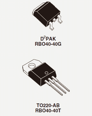
The 40 amp rating itself makes the device immediately suitable for all high current motor and inverter application in the form of  a freewheeling diode for countering the dangerous back EMFs, which becomes a serious issue with all such applications.

Although this versatile diode may be ideally suitable as a freewheeling diode and also in the form of blocking diode for safeguarding against reverse battery polarity, the device includes a special over voltage protection for countering voltage surges and load dumps.

As per the datasheet, the device is assigned with the following features:

  • In-built spike protector for safeguarding against "load dump" voltage pulses.
  • Can be used as regular 40 amp blocking diode for countering accidental battery polarity reversal.
  • A Monolithic structure ensures improved reliability
  • Breakdown voltage is not above 24V, so here the feature may be restricted within this limit.
  • Spike clamping voltage is set at +/- 40V

The absolute maximum ratings of the RBO40-40G/T may be studied from the following data:

  • Instantaneous (10ms) non-repetitive surge peak forward current limit is 120Amps
  • Continuous DC forward current handling capacity is 40 amps
  • Instantaneous peak load dump voltage handling capacity is 80V
  • Instantaneous peak power handling capacity is 1500 watts

 Internal Layout Description

40 Amp Diode RBO40-40G/T internal layout

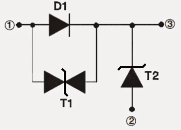
Referring to the above figure which shows the internal structure of the diode, the involved three main functions of the device may be understood as given under:

1) The indicated diode D1 is assigned for functioning in the standard rectifier diode mode for safeguarding against accidental battery reversal.

2) T2 component associated with the device acts like an effective transil to counter against positive peak transients pulses or back EMFs which may be generated by the associated high power relays, inductors, ignition coils, transformers, motor winding etc.

3) The third part T1 which can be seen in the internal layout of the device is specifically included for motor applications to protect the transistors drivers from the motor coil back EMFs or negative voltage spikes.

Pinout Details

The pinout configuration or the connection details of the proposed 40 amp diode with reverse and overvoltage protection can be seen in the following diagram. Nothing looks complex in the design, it's just about connecting the leads as per the correct polarity, and getting maximum protection from reverse voltage, transients, spikes, over-voltages etc in a circuit which may be highly prone to such parameters.

pinout configuration or the connection details of  40 amp diode

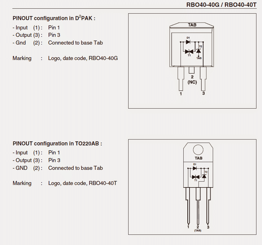
Courtesy: st.com/web/en/resource/technical/document/datasheet/CD00001320.pdf

You'll also like:

  • 1.  Electronic Component Buying Guide for New Hobbyists
  • 2.  High Voltage Transistor MJ11021(PNP) MJ11022 (NPN) Datasheet – Complementary Pair
  • 3.  IC 4040 Datasheet, Pinout, Application
  • 4.  TSOP1738 Infrared Sensor IC Datasheet, Pinout, Working
  • 5.  BC636 Transistor Datasheet [45 V 1 Amp PNP Transistor]
  • 6.  How to Understand and Use white LEDs – Datasheet

About Swagatam

I am an electronics engineer with over 15 years of hands-on experience. I am passionate about inventing, designing electronic circuits and PCBs, and helping hobbyists bring their projects to life. That is why I founded homemade-circuits.com, a website where I share innovative circuit ideas and tutorials. Have a circuit related question? Leave a comment.... I guarantee a reply!

Previous Post: « Multilevel 5 Step Cascaded Sine Wave Inverter Circuit
Next Post: Bathroom Lamp Timer Circuit with Buzzer »

Reader Interactions

Comments

  1. C K Chatterjee says

    September 1, 2022 at 1:12 pm

    Can we use it for transformer dc winding resistance test. Is it protects the test equipments from transformer back emf which is produced during switch of the dc source.pls advice.

    Reply
    • Swagatam says

      September 1, 2022 at 1:39 pm

      It can be used to protect from transformer back EMF but I am not sure whether this diode can be used for transformer DC resistance test or not.

      Reply
  2. kraken says

    November 2, 2017 at 5:09 pm

    ?dl=0" rel="nofollow ugc">comment image?dl=0
    done changing. can you take a look again? pelase

    Reply
    • Swagatam says

      November 2, 2017 at 5:19 pm

      the diode polarity is incorrect, the band side must be towards the ground.
      the S/D is correctly written but the symbol i wrong…you should draw it correctly to avoid confusions.

      do not remove the earlier 10V zener, connect it bck across gate/source

      Reply
      • kraken says

        November 2, 2017 at 7:36 pm

        ?dl=0" rel="nofollow ugc">comment image?dl=0
        i corrected the drawing of mosfet., and reverse the zener(1n4148)., can you take a look for the last time? please

        Reply
        • Swagatam says

          November 2, 2017 at 9:10 pm

          It looks fine now, but the zener cathode must be connected with the source side of the mosfet

          Reply
  3. kraken says

    November 2, 2017 at 2:00 pm

    hi swatagam,
    i tried my project to protect the battery and solar pannel can you please look at my link?
    ?dl=0" rel="nofollow ugc">comment image?dl=0

    Reply
    • Swagatam says

      November 2, 2017 at 3:38 pm

      Hi Kraken, If you are trying to charge the battery from the solar panel and through the MPPT controller, then I am afraid in the shown position the P-channel mosfets will not conduct, because their polarities look reverse biased.

      the right side mosfet source should go to the solar panel positive, and the left side mosfet source should go to the MPPT positive.

      Reply
      • kraken says

        November 2, 2017 at 3:58 pm

        what could be my solution to protect the mppt from reverse polarity both sides.

        Reply
        • Swagatam says

          November 2, 2017 at 4:41 pm

          interchange the source/drain pins, and connect a 1N4148 series diode between the gates and the ground line, cathode to ground, anode to the 100K resistor.

          Reply

Need Help? Please Leave a Comment! We value your input—Kindly keep it relevant to the above topic! Cancel reply

Your email address will not be published. Required fields are marked *

Primary Sidebar

Subscribe to New Circuit Ideas

Categories

  • Arduino Projects (87)
  • Audio and Amplifier Projects (132)
  • Automation Projects (17)
  • Automobile Electronics (101)
  • Battery Charger Circuits (82)
  • Datasheets and Components (103)
  • Electronics Theory (143)
  • Free Energy (37)
  • Games and Sports Projects (11)
  • Grid and 3-Phase (19)
  • Health related Projects (25)
  • Home Electrical Circuits (12)
  • Indicator Circuits (14)
  • Inverter Circuits (87)
  • Lamps and Lights (142)
  • Meters and Testers (69)
  • Mini Projects (46)
  • Motor Controller (64)
  • Oscillator Circuits (27)
  • Pets and Pests (15)
  • Power Supply Circuits (108)
  • Remote Control Circuits (50)
  • Security and Alarm (64)
  • Sensors and Detectors (101)
  • Solar Controller Circuits (59)
  • Temperature Controllers (42)
  • Timer and Delay Relay (49)
  • Transmitter Circuits (29)
  • Voltage Control and Protection (37)
  • Water Controller (36)

Calculators

  • Battery Back up Time Calculator
  • Capacitance Reactance Calculator
  • IC 555 Astable Calculator
  • IC 555 Monostable Calculator
  • Inductance Calculator
  • LC Resonance Calculator
  • LM317, LM338, LM396 Calculator
  • Ohm’s Law Calculator
  • Phase Angle Phase Shift Calculator
  • Power Factor (PF) Calculator
  • Reactance Calculator
  • Transistor Astable Calculator
  • Transistor base Resistor Calculator
  • Voltage Divider Calculator
  • Wire Current Calculator
  • Zener Diode Calculator
  • Filter Capacitor Calculator
  • Buck Converter Calculator
  • Boost Converter Calculator
  • Solar Panel, Inverter, Battery Calculator
  • Wire Current Calculator
  • SMPS Transformer Calculator
  • IC SG3525, SG3524 Calculator
  • Inverter LC Filter Calculator

People Also Search

555 Circuits | 741 Circuits | LM324 Circuits | LM338 Circuits | 4017 Circuits | Ultrasonic Projects | SMPS Projects | Christmas Projects | MOSFETs | Radio Circuits | Laser Circuits | PIR Projects |

Recent Comments

  • Swagatam on Best Electronic Circuit Projects
  • TOMMY on Best Electronic Circuit Projects
  • Swagatam on Inverter Circuit with Feedback Control
  • Jerry Adeosun on Inverter Circuit with Feedback Control
  • Swagatam on Contact

Company

  • Privacy Policy
  • Cookie Policy
  • About Me
  • Contact
  • Disclaimer
  • Copyright
  • Videos
  • Sitemap

Social Profiles

  • Twitter
  • YouTube
  • Instagram
  • Pinterest
  • My Facebook-Page
  • Quora
  • Stack Exchange
  • Linkedin
  • © 2025 · Swagatam Innovations