• Skip to main content
  • Skip to primary sidebar

Homemade Circuit Projects

Need circuit help? Post them in the comments! I've answered over 50,000!

Blog | Categories | About | Contact | Calculators-online
You are here: Home / Datasheets and Components / BC636 Transistor Datasheet [45 V 1 Amp PNP Transistor]

BC636 Transistor Datasheet [45 V 1 Amp PNP Transistor]

Last Updated on March 18, 2023 by Swagatam 3 Comments

The BC636 is a PNP bipolar junction transistor (BJT) that is specifically designed for low noise amplifier and switching applications. Here's the complete datasheet of the transistor BC636.

Table of Contents
  • Pinout Configuration
  • Electrical Characteristics:
  • Package Details:
  • Operating Conditions:
  • Applications:

Pinout Configuration

warning message: electricity is dangerous, proceed with caution
BC636 pinout diagram

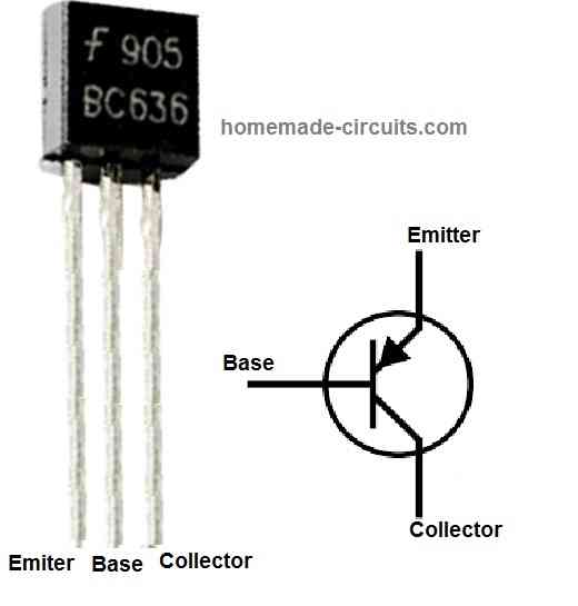
Referring the pinout diagram above, the BC636 transistor 3 pinouts.

  • Pin#1 = Emitter
  • Pin#2 = Base
  • Pin#3 = Collector

Electrical Characteristics:

  • Collector-Emitter Voltage (VCEO): 45V
  • Collector-Base Voltage (VCBO): 60V
  • Emitter-Base Voltage (VEBO): 5V
  • Collector Current (IC): 1A
  • Power Dissipation (PD): 625mW
  • DC Current Gain (hFE): 100-630
  • Transition Frequency (fT): 150MHz
  • Noise Figure (NF): 4dB

Package Details:

  • The BC636 transistor is available in a TO-92 package, which is a small, through-hole package that can be easily mounted onto a circuit board.

Operating Conditions:

The maximum operating temperature for the BC636 is 150°C.

The recommended operating conditions for the transistor are as follows:

Collector-Emitter Voltage (VCEO): 45V

Collector Current (IC): 1 A

Operating Temperature: -55°C to 150°C

Applications:

The low noise characteristics and high transition frequency of the BC636 make it suitable for use in low noise amplifier circuits.

The high current rating of the transistor also makes it suitable for use in switching applications.

Other applications for the BC636 include audio pre-amplifiers, audio amplifiers, and RF amplifiers.

You'll also like:

  • 1.  Understanding IC 4043B, IC 4044B CMOS Quad 3-State R/S Latch – Working and Pinouts
  • 2.  55V 110A N-Channel Mosfet IRF3205 Datasheet
  • 3.  LM311 Datasheet, Circuit Applications
  • 4.  Unijunction Transistor (UJT) 2N2646 Datasheet
  • 5.  220V Solid State Relay (SSR) Circuit using Triac and OptoCoupler
  • 6.  2N3906 Datasheet [40V, 200 mA, PNP Transistor]

Filed Under: Datasheets and Components Tagged With: BC636, Datasheet, PNP, Transistor

About Swagatam

I am an electronics engineer and doing practical hands-on work from more than 15 years now. Building real circuits, testing them and also making PCB layouts by myself. I really love doing all these things like inventing something new, designing electronics and also helping other people like hobby guys who want to make their own cool circuits at home.

And that is the main reason why I started this website homemade-circuits.com, to share different types of circuit ideas..

If you are having any kind of doubt or question related to circuits then just write down your question in the comment box below, I am like always checking, so I guarantee I will reply you for sure!

Previous Post: « Diodes: Working, How to Use, Applications
Next Post: Child Crying Monitor Circuit using Power Line Communication »

Reader Interactions

Comments

  1. Swag says

    March 21, 2023 at 6:11 pm

    Good article!

    Reply
    • Swagatam says

      March 21, 2023 at 6:11 pm

      thank you!

      Reply
    • Swagatam says

      March 21, 2023 at 6:16 pm

      Let me know if you have further questions

      Reply

Need Help? Please Leave a Comment! We value your input—Kindly keep it relevant to the above topic! Cancel reply

Your email address will not be published. Required fields are marked *

Primary Sidebar

circuit simulator image

Subscribe to get New Circuits in your Email


Categories

  • Arduino Projects (89)
  • Audio and Amplifier Projects (132)
  • Automation Projects (17)
  • Automobile Electronics (101)
  • Battery Charger Circuits (83)
  • Datasheets and Components (105)
  • Electronics Theory (143)
  • Free Energy (37)
  • Games and Sports Projects (11)
  • Grid and 3-Phase (19)
  • Health related Projects (25)
  • Home Electrical Circuits (12)
  • Indicator Circuits (14)
  • Inverter Circuits (88)
  • Lamps and Lights (142)
  • Meters and Testers (69)
  • Mini Projects (46)
  • Motor Controller (64)
  • Oscillator Circuits (28)
  • Pets and Pests (15)
  • Power Supply Circuits (108)
  • Remote Control Circuits (50)
  • Security and Alarm (64)
  • Sensors and Detectors (102)
  • Solar Controller Circuits (59)
  • Temperature Controllers (42)
  • Timer and Delay Relay (49)
  • Transmitter Circuits (29)
  • Voltage Control and Protection (40)
  • Water Controller (36)


Other Links

  • Privacy Policy
  • Cookie Policy
  • Disclaimer
  • Copyright
  • Videos
  • Sitemap

People also Search

555 Circuits | 741 Circuits | LM324 Circuits | LM338 Circuits | 4017 Circuits | Ultrasonic Projects | SMPS Projects | Christmas Projects | MOSFETs | Radio Circuits | Laser Circuits | PIR Projects |


Social Profiles

  • Twitter
  • YouTube
  • Instagram
  • Pinterest
  • My Facebook-Page
  • Quora
  • Stack Exchange
  • Linkedin


  • Recent Comments

    • Swagatam on Sine wave PWM (SPWM) Circuit using Opamp
    • Swagatam on 5 Simple DC Motor Speed Controller Circuits Explained
    • lameck on 5 Simple DC Motor Speed Controller Circuits Explained
    • Rod. Cripps on Sine wave PWM (SPWM) Circuit using Opamp
    • Swagatam on 3 High Power SG3525 Pure Sine wave Inverter Circuits

    © 2025 · Swagatam Innovations