A simple barcode security lock circuit or barcode scanner circuit is explained in the following article using just a handful of ordinary components such as an op amp, an LDR and an laser light.
We all have seen and are familiar with these arrays of thick and thin lines which can be seen printed on almost all types of products, these coded arrangement is commonly known as a bar code.
A barcode strip printed on a particular product identifies quite a few crucial information regarding the product in an encoded form.
How Barcode Scanners Work
Barcode scanners are sophisticated instruments which are used for scanning bar codes for decoding the hidden information of the product for the required purpose.
Normally these devices consist of a laser beam which is thrown across the barcode, the light gets reflected from the white portions of the barcode whereas its absorbed in the black lines of the code.
The above reflected varying light intensities are appropriately captured by a photosensor and translated into a varying analogue frequency output.
The above analogue data is then converted into digital pulses through a circuit stage and these digital pulses are further converted into binary form for feeding into a PC or a software. The software finally decodes the information by recognizing the digital/binary pattern of the fed data.
Making a Barcode Scanner Circuit
A simple homemade barcode scanner is presented in the following discussion which can be used for experimenting and playing with different barcoded strips and for customizing it as a security key lock device.
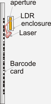
Referring to the couple of diagrams below, the diagram on the left shows a LED/LDR sensor which may be positioned close to the barcode strip inside an appropriate box enclosure for sensing the barcode specification.
How the Concept Works
When the barcode card is swiped, the laser beam is reflected from across the black/white barcode lines with varying intensities and is received/detected by the LDR through an appropriately drilled aperture, as may be visualized in the left diagram above.
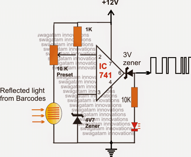
The barcode security lock circuit on the right shows a simple opamp comparator circuit integrated with the LDR sensor for translating the barcode data into a correspondingly varying digital signals
The 10 k preset is subtly set such that the opamp is able to respond even to the minutest difference in light sensed by the LDR.
Thus the varying light intensities from a swiping barcode card is quickly responded by the opamp and is converted into a correspondingly changing rectangular waveform across its pin6.
Since here we are only interested to use the decoded information to uniquely activate a compatible lock and key arrangement, reading only the frequency and the RMS would be sufficient for using the barcode info as a potential security locking/unlocking data.
In the next post we'll learn how to make a barcode decoder circuit or activating a relay mechanism.
Designing a Barcode Activated Security Lock Circuit
So far I have explained about a simple barcode sensor circuit, now we'll study how the sensed pulses can be transformed for getting unique sets of high low outputs from the IC 4033 in response to different barcodes patterns. This unique results can be then used for activating a barcode security lock circuit or an alarm.
The idea is based on the fact that the lines of the bar code have different thicknesses and this could be scanned to produce unique time intervals across the entire bar code design.
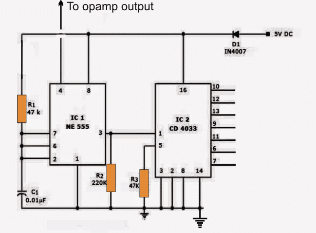
In the figure below we see the circuit design for creating unique 7 segment outputs in response to the opamp sensor feed.
How it Works
In the proposed barcode security lock circuit, a 4033 IC which is a 7 segment decoder is used with a IC 555 clock generator for generating the unique results in response to the barcode.
Pin4 of the IC 555 is connected with the op amp sensor output which implies that the IC 555 will be active and run the IC 4033 only for the white spaces on the barcode, since the white spaces are supposed to create high logic pulses across the opamp output will keep the IC 555 pin4 reset pin activated during these periods.
And while the IC 555 is clocking, IC 4033 would be busy creating the BCD sequences across its output pins, and across the black lines of the barcode this sequence generation will stay inhibited.
Now in order to get a uniform and consistent outputs from the IC 4033 for individual barcode, the barcode card needs to be swiped using a motor mechanism or a solenoid mechanism with a regulated constant speed and not with hand.
The motor could be operated with a set/reset mechanism such that it moves the entire barcode length in front of the laser/LDR assembly.
The motor switch ON could initiate the opamp circuit which then starts sensing the barcode pulses to transform it into a PWM form.
This PWM is quickly responded by the IC 555/4033 circuit until the entire barcode is read.
As soon as the reading ends the outputs of the 4033 stay latched with a unique set of high and low outputs.
These outputs can be individually configured with relay mechanisms in order to activate an electrical lock, a gate, or any intended security system.
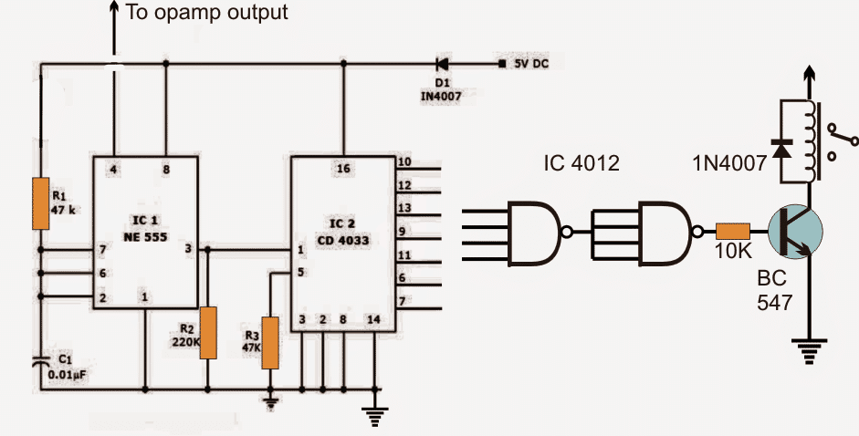
A 4 input NAND gate IC 4012 could be used and configured with any four selected unique outputs of the decoder for activating a security relay.
If 3 high outputs are selected then one of the NAND inputs could be shorted to the positive supply.


Questions & Answers
Hi, I can’t work out how to contact you other than commenting…My friend has written his story (A Technician’s Tale) and I’m creating the book cover for him. He was an electronics engineer and I thought it would be fun to put the barcode into the scanner circuit diagram and I wanted to ask your permission to use your image? I’d like to use the last image that comes after “These outputs can be individually configured with relay mechanisms in order to activate an electrical lock, a gate, or any intended security system.”
The book will be sold among friends and if any profits are ever made he has in mind to donate the money.
Please feel free to reply directly to my email if you’d like to delete this comment and keep the conversation thread clean.
Hi, you can feel free to use any circuit diagram you wish for your personal application, I have no issues whatsoever.
Thank you, really appreciate this 🙂
Hi Swagatam,
Is it possible to make the circuit from barcode scanner output converted into digital output? If you have the circuit, can you please share with me.
Thanks.
Sorry Kanagaraj, I do not have the circuit at this moment.
Thanks Swagatam,
But I want to know, what type of output in barcode scanner? Is it digital or analog or any other type output?
We’re can I get the codes for this homemade barcode security lock system
Hi Kanagaraj, It is always digital according to me.
Hello Sir,
I saw that you mentioned if someone would like personalized help, to contact you through this comment form.
I am intrigued by this “How to Make a Barcode Security Lock Circuit”, and looking to develop a similar type system for my grandmother’s rental homes.
I looked throughout your site and didn’t see anything about wifi or cell phone app controlled door lock devices.
Are you familiar with the way the wifi interaction, through the cell phone, would allow you to control a door lock on a home?
I want to make something for her, so she can control access to her rental homes, via her computer, enabling and disabling user access, whenever she wishes.
She has been robbed so many times, due to people making additional keys, and even giving out access push button codes, when we updated at great cost, to access panel, push button code locks for her homes.
I saw another company that made something similar, called Lockitron, but she didn’t like it, and wants to be able to change the access at anytime, and for multiple users possibly.
She liked the bar code idea, but wanted to know if the bar code could be changed remotely, from her computer, on the door lock itself, so if she was to send them a new bar code, it would be able to access the door lock, as soon as she updated the bar code on the device, via her computer or wifi connection.
Basically, access needs to be able to be changed any time, and updated through her computer or by cell phone.
She could send them a new bar code, or a new access push button code, even, and have total control over the access, without having to have someone else go out, since she can’t walk anymore, and drive, to change the key lock or program code on the push button panel, physically, on site.
I know this is a lot, but I thought I might ask, and she reminded me you stated to ask if there were any personal requests, so here I m asking if it is anything you are familiar with, and how it would be done.
I absolutely love your site.
I am learning and it is extremely helpful that there is someone that cares enough to share their knowledge with others, as is not very common these days.
Thank you much, Mike(grandson) & Grandma!
Hello Mike, Thanks for posting your requirement, I appreciate your interest, and I do love addressing personalized requirement, however controlling something through Wi-Fi is at the moment beyond the scope of my knowledge. If you have anything simpler than this, I can definitely give it a try.
Hi Swagatam
Nice idea, to build a cheap bar code card reader.
Thank you Abu-Hafss!