This simple circuit will enable you to visualize distant thunder lightning through a correspondingly choreographed LED flashes, exactly in accordance with the lightning that may be taking place somewhere in the distant sky, the response will be simultaneous and thus much prior to the sound that may reach your ears after a few seconds.
RF from Thunder Lightening
Thunder lightnings are basically like huge electric arcs, and thus generate a proportionate amounts of huge RF signals in the ether every time these flash in the sky.
The tiny RF detector circuit which was initially developed for catching cell phone RF waves, could be as effectively used for the proposed lightning detector design as well.
Circuit Diagram
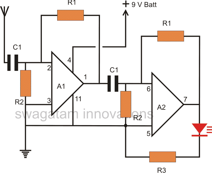
Parts List R1 = 2M2,R2 = 100K,R3 = 1K, C1 = 0.01uF, A1, A2 = IC 324
Referring to the above simple thunder lightning detector circuit, the configuration is basically a couple of opamps from the IC LM324 wired up as a high gain amplifier circuit.
Antenna Specs
The antenna could be a meter long flexible wire used here for receiving the RF disturbances from the thunder lightning arcs.
Since the circuit is a high gain amplifier, it could become easily upset and give wrong results if certain things are not taken care of.
All the interconnections must be as small as possible, and the PCB must be thoroughly cleaned with thinner in order to remove any sort of flux residue which could otherwise create malfunctioning of the circuit.
How to Test the Setup
After constructing the above design, initially do not connect any wire to the antenna terminals.
Make sure the LED stays shut off after the circuit is powered, and use a 9V PP3 battery for powering the circuit, an AC/DC adapter will not work as you will see the LED always ON if a mains adapter is used.
Next, take a gas lighter and click the device with its tip held close to the antenna point of the circuit.
You should find the LED illuminating and flashing in response to every clicking of the gas lighter.
This would confirm a correctly built detector circuit.
Video Illustration
Connecting the Antenna
Finally, you can attach the 1 meter long antenna wire to the shown position and wait for a possible thunder lightning strikes in the vicinity.
You will be surprised to see the LED dance and flash exactly in tandem with the lightning illumination sequences.
You could amplify the Led response by adding an opto coupler and a corresponding high watt lamp with the circuit, such that the whole room gets dazzled each time the lightning flashes in the sky.
Important Criteria
Please note that in order to ensure 100% working of this circuit, you will have to use a battery as the DC supply for the circuit. And connect the negative line of the circuit with some kind of earthing line. In my case I connected it with my bathroom tap.
Wait...I don't quite remember whether the earthing is required or not if a battery is used. May be I had used an adapter as the supply and therefore I had to use the external earthing for suppressing the 50Hz disturbance....please confirm this at your end!
And make sure the antenna wire is very long. In my experiment I used a 2 to 3 meter long flexible wire.
For testing you can try clicking your gas lighter near the antenna, the LED must respond with corresponding blinking.
I happened to discover this unique property of this circuit as a thunder lightning detector accidentally, while testing for mobile RF detection. Thankfully it was rainy season then, otherwise I could have never come across this outstanding feature of this circuit.
Using 10 LED Display
In this design you can visualize and assess the strength of an approaching thunder storm and lightening, through a 10 LED bar graph display.
The up/down movement of the LED on the bar graph will provide a direct indication of how strong or how near the thunder storm may be.
The entire circuit diagram of the 10 LED based thunder storm lightening detector can be seen in the following diagram.
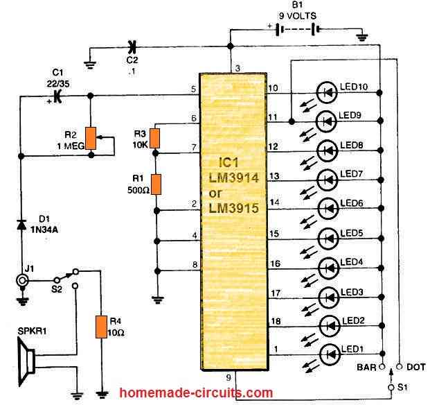
It is basically a 10 LED LM3915 driver circuit integrated with a AM radio.
Yes, you will need a small AM radio which can be connected with the LM3915 circuit through the radio headphone jack.
Alternatively, the circuit has a small speaker which can be held close to the speaker of the radio.
An AM radio being a very sensitive thunder lightening detector will detect an approaching thunder storm and reproduce the sound of the thundering on its speaker. This sound from the radio speaker will hit the LM3915 speaker and convert the results into an incrementing LED illumination on the bar graph providing a direct display of how strong the distant thunder lightening may be.
Lightning VLF and HF Monitor Circuit
It is well known that lightning strikes which hit the ground instead of clouds produce significantly higher VLF (Very ow Frequency) emissions. The ratio of cloud-to-ground or cloud-to-cloud discharge, hits per flash, leader steps, amplitude, and relative range may all be determined by observing both VLF and HF (High Frequency).
This straightforward receiver can keep an eye on both HF and VLF signals. The device could let you to remain indoors during a thunderstorm and shield you from the downpour and 100 kilojoule discharges.
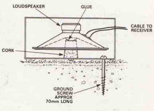
How to Make the Antenna Coil L1
The antenna coil L1 may be constructed to detect and monitor VLF by winding 94 rounds of 33-gauge magnet wire around an 11-inch cardboard disc. To monitor HF from lightning strikes, the antenna coil (L1) could be a standard RF choke.
Alternatively, L1 could be constructed using around 100 turns of extremely tiny magnet wire on a 1/2-inch-long ferrite core (or any equivalent spare choke would suffice).
The antenna could be any 6-inch flexible wire.
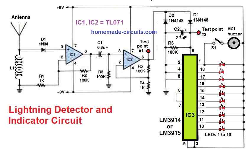
How the Circuit Works
The first TL071 FET operational amplifier is set up as a preamp. A second TL071 boosts the gain of the lightning detection. You can attach high-impedance headphones or an oscilloscope to test-point#1. After rectifying, the diode/resistor/capacitor components modify the output for quick attack/slow decay.
The second test point #2 is for connecting to chart recorders or event counters.
The circuit's outputs are connected to low-voltage piezo buzzers BZ1 and LM3914 bargraph display drivers IC3.
IC3 outputs illuminate the LED bargraph sequentially in response to lightning detection. Dual 9V supplies are used to power the circuit.
How to test
Make use of the two separate coils for L1 and power the circuit during the tests. For the HF coil on L1, a decent broadband source of noise, for example a light dimmer, should be detectable on the LED graph.
When VLF coil is used for L1, switching a far away incandescent light on and off repeatedly should allow the LEDs to run sequentially in response to the VLF.

Questions & Answers
Hello Swagatam, You have given a very detailed information on the lightening and Thunder detector using operational amplifier tl071 , but can we use the operational amplifier 741 instead of tl071?
It would be great help if you let us know about this.
THANK YOU FOR THE INFO.
Thank you Shivani, glad you found the circuit interesting.
I think IC 741 can be used in the last circuit because it’s just an RF amplifier and the audio output quality is not critical.
However, the last circuit was not designed by me, it was contributed by an external author.
The first circuit was designed by me and is fully tested.
Okay, But I had got the problem statement of designing the Circuit of lightening with different frequencies using opamp ua741 ic and aurdino uno.
Can you pls tell me how to proceed in this?
You can provide me the Arduino working specifications, if possible I will try to figure it out. You can try the 741 IC in the first circuit, using the single opamp only, and check whether it works or not.
What should the actual inductance values for the 2 inductors be?
please i would desire an mppt change controller circuit using the PIC16F876A the load is a minimum of 12V battery, the input is a minimum of 150W solar panel. other features will have a display, LED indicators and an alarm.
My microcontroller knowledge is not good, so working with a PIC can be difficult for me….
Hi, if you could use any other microcontroller other than a PIC for the same circuit requirements that will be perfect as well.
My programming knowledge is not good so it is difficult for me to work with any kind of microcontroller.
Hi Swag,
Can I use LM358 in this circuit?.
LM324 has 4 ampop and 2 will be wasted.
LM358 only has 2.
Best Regards.
Hi Jan, I think if LM324 works then LM358 should also work, since both have op amp with similar characteristics… You can try it.
Hi. Can I use an AM radio to detect lightning activity?
Yes that’s another way to detect thunder lightening.
Hi
Can you please suggest what can be done if the led remains on after the circuit is powered?
Hi, did you use a 9V battery for the circuit? If yes you can try reducing the R1 values to 2m2 instead of 10M, this will reduce the overall sensitivity of the circuit, then you can gradually increase its value to check at what point it becomes too much sensitive?
Please remember that the ground line of the circuit must be also connected with a perfect “earthing”…in my experiment I connected it with my bathroom water tap.
Otherwise the circuit will fail to work as a thunder sensor
Yes i have usedd a 9v battery for the circuit but the resistance i selected is 2M .
with 2m and a battery supply the LED should not remain lit…try reducing the 2M to 100k, if still the LED remains ON then the problem could be somewhere else….
hi swag, after i connected the circuit, i tried to test the circuit with gas lighter at the end of small wire connected with the capacitor of the connected circuit but the LED did not light up, i already tried many debugging but still the same. can you give me any way for me to send a picture of it so you can have a closer look of the circuit and tell got any prblm.thank you
Hi khgoh, the circuit was tested by me long ago around 6 years ago while designing a mobile RF detector. During those experiments I could make it work as a thunder detector and also as a gas lighter detector….I do not remember all the details of the experiment now…I may have to conduct the experiment again to update all the required details.
The schematic is perfect no doubt about it, so even if you send the schematic I may not be able to find the fault unless I check it practically…if possible I’ll do it again and let you know. make sure to use a 9V battery for the experiment.
Good morning sir khalid here how are you sir please take care sir i will pray allah for your well being. Sir i make the circuit but the led not work with lighter when i touch finger to ground led glows but very dim i am using 1 meter long flexible wire and i make ionizer circuit from your article i took the antena near to ionizer corcuit the led still glowing very dim so what could the problem i am using 10m resister plesae reply i wi be thank full waiting for reply thanks.
Hi Khalid, as you can see the circuit is very straightforward and should work without any issue. Please check all the connections properly, and also make sure the op amp is not faulty, check the LED also separately
You can also refer to the following post for more info:
Anti Spy RF Detector Circuit – Wireless Bug Detector
Hi sway,
Only the A1 pin 11 connected to ground right, no need for the A2 right?
That’s right, because the opamps are from a single IC LM324
Hi,
Kindly give me an example of antenna that can be used in this project, as i have difficulties to find for it, maybe a picture or sample of the antenna will be really helpful.. thank you so much sir/madam
Hi, use just a long flexible wire that’s all, but make sure to have an earthing also. I think I had use the earthing since the supply was from a mobile charger, and the “earthing” perfectly stabilized the system for the reception
Hi,
can i know what type of antenna is used for this circuit, and is there circuit available to track thunder sound, its a prototype project, a piezo lighter will be used for lightning strikes and the thunder sound will replace by hand tapping sound and arduino will be coded accordingly to display time interval between the two happenings.
Kindly advice for more information needed.
Hi,
In my prototype I had used a long flexible wire as the antenna, around 3 meters long, and had used my kitchen tap metal for the earthing, the power was supplied from a 9V PP3 battery.
I do not have an Arduino distance calculator, however a 4017 IC based circuit is there with me which was published in one of the old elektor electronic magazine…I’ll try to present it if possible.
Hi,
is telescoping antenna or omni directional antenna suitable with this circuit design and if so what modification is necessary?
any long wire should do, no need of specialized antenna…
Low cost habby circuit like clap switch on or off time delay timer touch switch switch dark detactor switch ic ne555 cd 4017 this type ic i hope you are must help tested circuit diagram
I have all these circuit in this website, you can try them, all are tested….
Hi I am raja dora i have electronic trande but how to built habby circuit can you help me kindly
You can ask any related question I will try to explain…
Can get any idea about smart office
Plzzz it is for my project
If u hv any idea plzzzz send me okey
Or send circuit to my e-mail
Naushadnausu27@gmail.com
I like this lightning detector circuit very much. When I built it on the breadboard, I got it working the first time. The thing that is a draw back is that it does not have enough sensitivity to receive distant lightning discharges. I hope a better version of this circuit could do distant lightning storms.
I am glad you could get the intended results so quickly, the circuit could be made more sensitive by entirely removing the 2M2 resistors or by replacing them with 10M resistors, or simply by adding two more opamps in series from the LM324 IC, however this would also mean the circuit getting so sensitive that it starts catching even minutest electrical disturbance happening in the vicinity.
It will work but it should be a battery, AC/DC adapter will not work
could this be used to trigger a camera in place of the led ? Would a metal reflector focus the antennae to a certain direction ?
sorry this is circuit is a simple RF sensor… such sophisticated integration won't be possible here
I was thinking about how to make the antennae directional so it was only sensitive in the direction the camera was pointing.
yes the LED trigger can be used for initiating a camera.
I could not understand the metal reflector concept??
Hi Swagatam
Wouldn't the operation of the circuit be interfered by the mobiles' RF signals?
Hi Abu-Hafss,
it will happen only if the mobile is activated inside the particular room, if it's in some neighborhood premise it won't affect much.
Moreover the LED illumination could be checked while a lightning may be occuring in the sky (during night) and compared, this would provide a clear proof of the happening, a later thundering sound would also complement the results perfectly:)