The following conversation was made by Mr.Tom and me regarding the circuit idea of a pyro-iginition system. I was asked to design the particular circuit idea by Mr.Tom in Fiverr.com.
Technical Specifications
The discussion explains the details of his requirement and how it was almost fulfilled by me
Hi Swagatam,
I was wondering if you could design me a system for a simple pyrotechnic firing system.
An input trigger would (maybe 5-12v) pulse would switch on que1, another pulse would switch cue2 (binary counter).
A total of 16 channels (cues), each cue would be fired with from mosfet pair. Ideally control circuit would have independent power supply to power to cues.
It would also be nice to have a timer which could on pulse fire each cue in sequence e.g. cue1 wait 1 second cue 2 wait 1 second cue3 etc.
Either this of some kind of programmable pic (picaxe etc) so the functionality can be changed.
Kind regards
Tom
Hi Tom,
I can design the control circuit along with the timer, however I'm interested to know what would be connected to the mosfet outputs, because that looks the difficult part if I'm required to set up those.
Thanks
Swagatam
Here's the pyro-ignition control circuit:
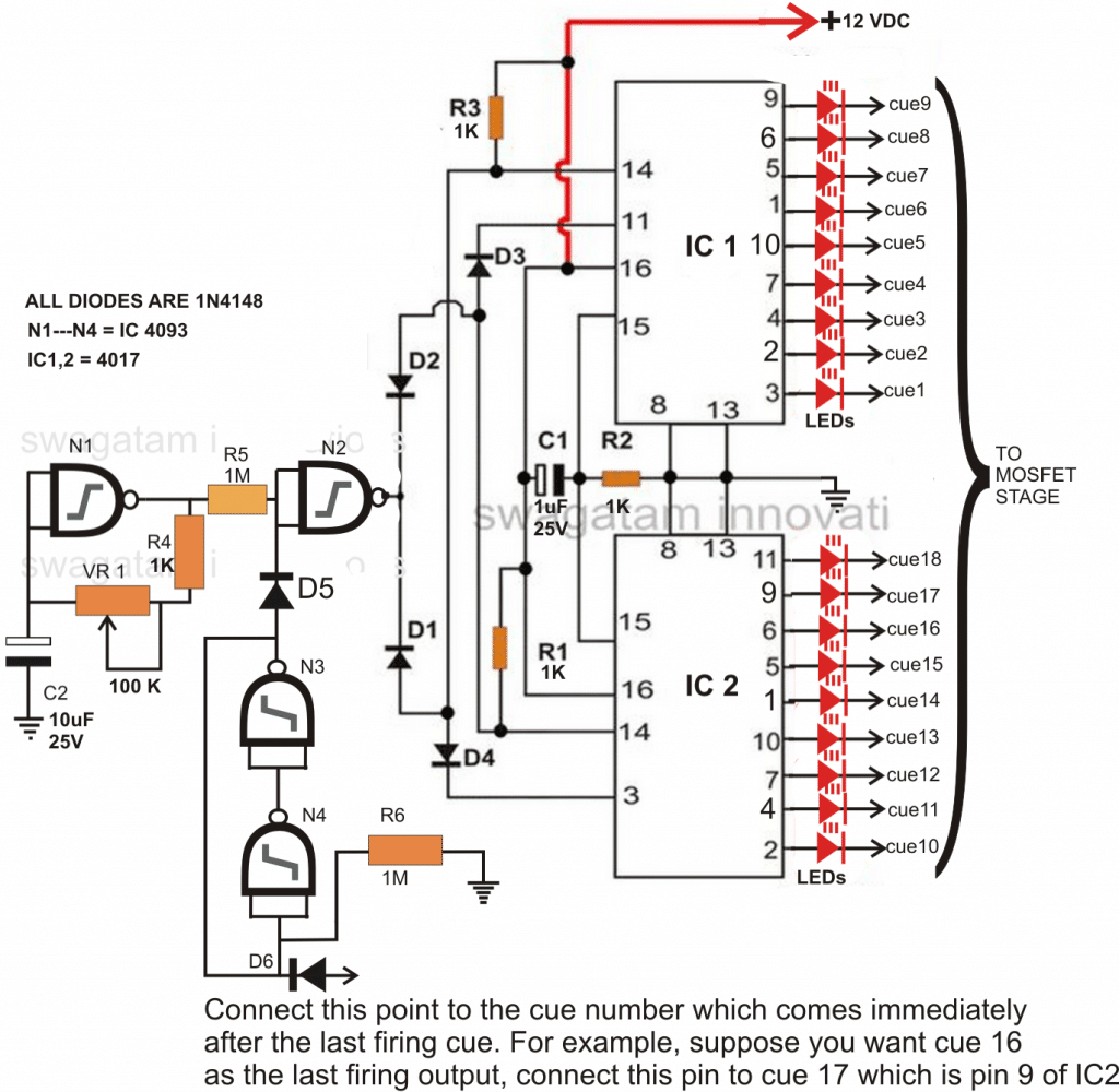
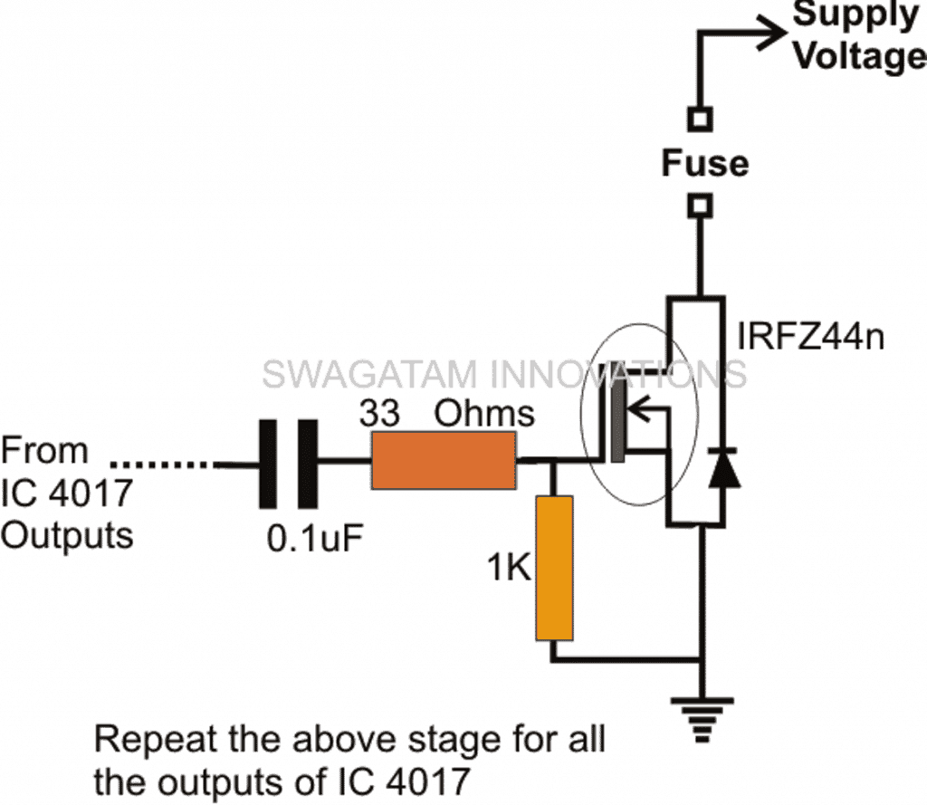
Next up is the mosfet output stage:
Hi Swagatam,
I don't seem to be able to get the control circuit to work.
Where does the external trigger connect to, if i connect a ground just before R5 can I use this as the trigger?
Thanks
Tom
Hi Tom,
The circuit starts sequencing the moment power is switched ON, so the "power ON" switch itself acts as the external trigger.
When power is switched OFF, the circuit resets and comes to its original state, so that when power is switched ON again, the cycle can repeats.
Thanks,
Swagatam
Hi Swagatam,
That's not what I asked for.
The external trigger should either start the timing sequence if selected or step through each output on each trigger input.
Referringback to the conversation
"
Function 1
Trigger -> Cue 1 fires (stays on for 100ms to ignite firework)
Trigger -> Cue 2 fires (stays on for 100ms)
Function 2
Trigger -> Fires all Cues in sequence (cue 1,2,3 etc) from a internal modifiable timer
Function 3
The circuit diagram also has continuity test for each cue, this should be a low enough current as not to fire igniter this is to be displayed through an led on each cue.
"
Regards
Tom
Hi Swagatam,
I've attached a circuit diagram of an open source wireless firing system, the files can be found here
http://code.google.com/p/openpyro/downloads/list.
The system will fire these http://www.category4.co.uk/igniters/technical/igniters.php
If you're just using a binary counter I think you might need to double the stages(bits) and pulse the clock after 100ms to turn off the mosfets in case of short circuit.
If you could replicate attached circuit without the wireless this would be fantastic. I'll pay for extra gigs if needed.
Thanks
Tom
Hi Tom,
From the above description what I understood is that the particular fireworks needs to be ignited in some sequence.
The fuses would be loaded across the relevant mosfets and the triggering timing would be such that the mosfets are switched only for some fraction of a second, just enough to ignite the fireworks and then shut off.
The sequence will go on repeating until the last mosfet is fired...am I correct?
If my interpretation is right then I can go ahead with the circuit and design it using ordinary discrete components, no need of any microcontrollers.
Thanks,
Swagatam
Yes,
Function 1
Trigger -> Cue 1 fires (stays on for 100ms to ignite firework)
Trigger -> Cue 2 fires (stays on for 100ms)
Function 2
Trigger -> Fires all Cues in sequence (cue 1,2,3 etc) from a internal modifiable timer
Function 3
The circuit diagram also has continuity test for each cue, this should be a low enough current as not to fire igniter this is to be displayed through an led on each cue.
Could this led be also lit when the cue is fired.
Tom
OK, function1 refers to a manual triggering option in the circuit? right?
There should be power to the circuit at all times, when a plus trigger is applied to the system it should step.
Hi Tom,
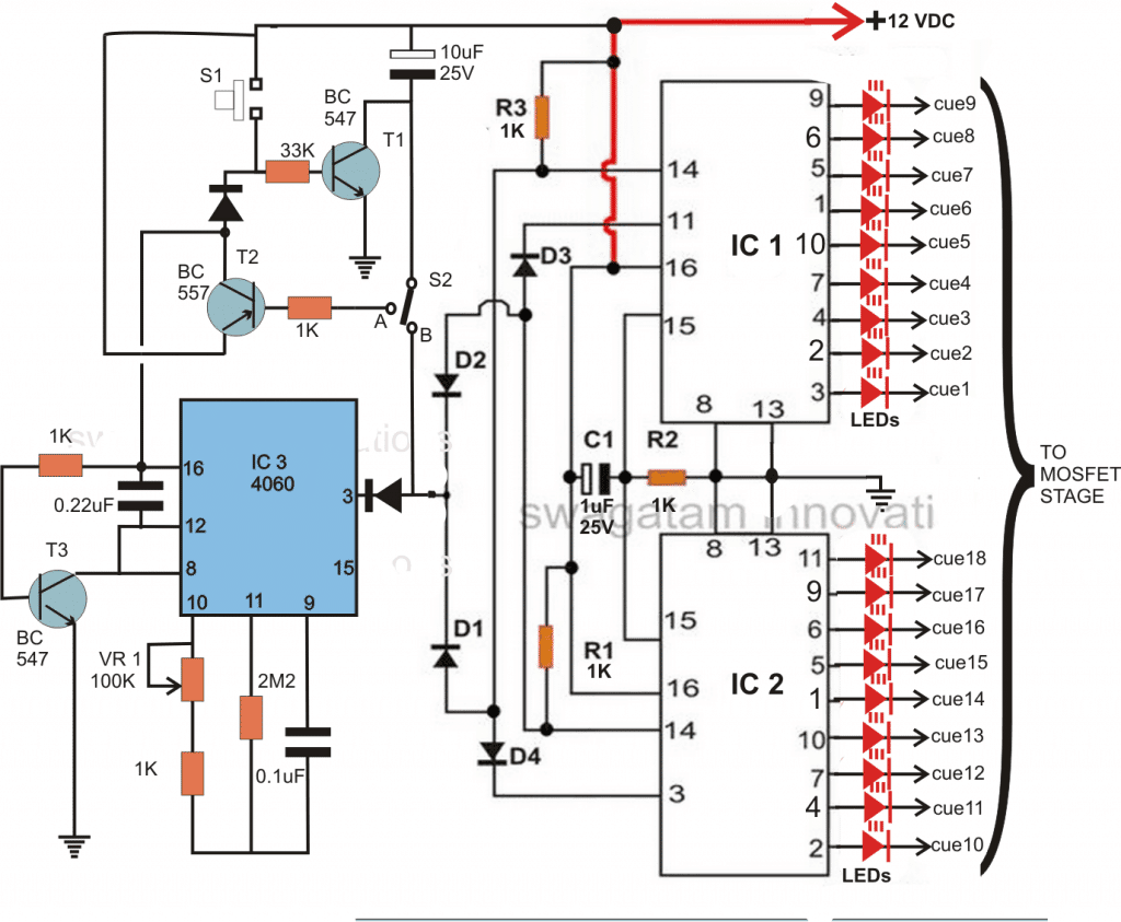
In our circuit this can be done through a simpler modification, kindly view the attachment.
Pressing S1 initiates the sequencing at any instant and releasing it stops the process.
Thanks
Swagatam.
OK let me try an explain again.
The circuit is a stepper, each trigger pulse it receives progresses the binary counter on one.
So trigger +12 v, binary counter increases one.
Trigger again +12v, binary counter increases one again.
The trigger pulse it totally separate from this circuit and comes from another source.
Easy enough, just a binary counter and outputs.
I also want another function to allow the first trigger pulse to start a timer a clock the binary counter on it's own. This time is variable. So there would be a switch to allow you to access this mode. So binary counter output 1 would feed back into the timer circuit if a switch was closed.
Hi Tom,
Just have a look at this modification, I hope this one works as intended.
S2 is a SPDT switch, when positioned toward B, it responds to the pressing of S1 and steps with each trigger from S1.
When S2 is moved toward A, pressing S1 does the following things:
T1 and T2 instantly latches powering the timer IC 4060 via T2 and T3.
IC 4060 starts clocking the IC 4017 for the required actions.
Putting S2 back to point B resets the circuit to its previous mode, that is to the manual mode. However to reset the IC 4017, it will need to be switched OFF and then switched ON again.


Questions & Answers
Thank you Swagatam.
I want to take advantage of your knowledge, lol.
I was told that I can use optocoupler, but as I don’t have enough wisdom, could you explain to me how to use it?
Thanks.
God bless you Swagatam!
Hi Carlos, no problem, you can also use an opto coupler to drive a MOSFET. You can try the following configuration:
Hi Swagatam,
I designed a fireworks system with Esp8266 (nodemcu) and a web page to control the fireworks. My problem is the part of the Mosfet, I tried to use your scheme but it seems that it does not work with 3.3V which is the output of Nodemcu.
Could you tell me how to do it.
Thank you very much in advance.
Carlos
Hi Carlos, you will have to lift the voltage to 12V for operating the mosfet using BJTs as shown below: Normally a mosfet will not operate properly with 3.3 volts gate drive.
hi, i am install pyro ignition control system of the link, where can i find the sketch of the arduino to conect to this program?
Schematic and Arduino sketch is in latest OpenPyro_v0.3.zip as available from the same Google link above.
Hi, sorry I have no idea about it…