A handful of simple DC over voltage protector crowbar circuits are discussed in this article. I have explained the working of each crowbar circuit through the following explanation.
What is Crowbar Circuit
If you are wondering what is a crowbar circuit, the definition is simple. It is a circuit network where a transistor or an SCR is used to monitor the output voltage.
As soon as the output voltage exceeds the set threshold the transistor or the SCR conducts short circuiting the supply terminals and blowing off a series connected fuse at the input.
The blowing of the fuse instantly cuts of the input supply preventing the output voltage from rising any further and thus protects the output load from an over voltage situation.
Simple Crowbar Circuit using SCR and Zener Diodes

Parts List
- Zener diode 5.6 V 1 watt, 9.1 V 1 watt= 1 each
- Resistor 56 Ω 1/4 watt = 1
- SCR BT151 = 1
- Fuse = 1
It is probably among the most simple crowbar circuit designs using just zener diodes and SCR. The circuit is easy to understand.
As soon the voltage across the supply rails starts to exceed a set threshold as determined by the zener diode value, the zener diodes breaks down and supplies the triggering voltage to the SCR gate.
The SCR instantly conducts and short circuits the supply rails forcing the fuse to blow and cut off the input supply. The cut off action protects the output load from an over voltage situation.
Crowbar Circuit without Fuse
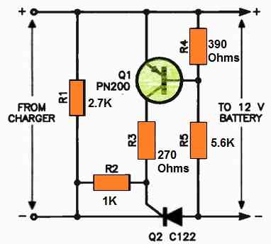
Parts List
- Resistors are 1/4 watt 1% MFR
- 2.7 k, 1 k, 270 Ω, 5.6 k, 390 Ω, = 1 each
- SCR C106 or BT151 = 1
- Transistor PN200 = 1
If you are interested to build a crowbar circuit without a fuse then you may find the above shown circuit quite useful.
You can employ this design in your battery charger to protect the battery from an over voltage situation as I have explained below.
The rectifier diodes in a battery charger could be protected against short circuits and reverse battery connections using a basic crowbar circuit.
The circuit makes use of the residual voltage that even a depleted lead-acid battery has. The circuit's crucial element, the SCR (Q2), is required to be energized by this voltage.
The SCR is triggered every half-cycle of the rectifier output when it rises over the battery voltage when the battery is connected correctly and the charger is switched on.
The battery may now receive current from the charger thanks to this.
The battery must be connected, and the leads must not be shorted or connected in reverse for the SCR to operate. By doing this, current is stopped and the rectifier diodes remain protected from damages.
The circuit also has a safety feature against 6V battery damage. The transistor Q1 won't turn on if a 6V battery is attached, which also prevents the SCR from turning on. This guards against a 6V battery being damaged by the charger.
Over-voltage Protector for 3-Terminal 78XX regulators
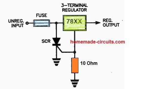
Parts List
- Any 3 terminal regulator = 1
- SCR BT151 = 1
- Resistor 10 Ω 1/4 watt = 1
- Fuse = 1
In order to switch ON an SCR crowbar circuit and blow a fuse in series with any 3 terminal regulator's input, you may utilize a three-terminal regulator's reference terminal bias current as crowbar over-voltage protection.
The reference current will source a significant increase in current if the unregulated input voltage increases too high, turning on the SCR and blowing the fuse.
You must pick a resistor that can generate enough bias to activate the SCR. Utilizing a sensitive-gate SCR is crucial as well.
Universal Crowbar Design for Protecting Power Supply Circuits
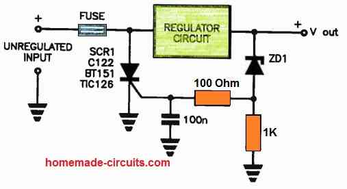
This circuit immediately shuts off the output if the series-pass regulator malfunctions, protecting a regulated power supply from excess voltage.
This stops the output from receiving the full unregulated voltage, which might harm the attached devices.
A zener diode, ZD1, is used in the circuit to detect an excessive voltage.
The voltage of the zener diode is selected to be slightly higher than the supply's maximum output voltage.
The zener diode conducts when the output voltage is higher than the zener diode's voltage. This current provides gate current to the SCR, Q1, through the bias resistor of the zener diode.
The fuse in series with the input of the regulator circuit then blows when the SCR conducts. This avoids the uncontrolled voltage by cutting OFF the regulator circuit from the power source.
Spikes cannot activate the SCR because of the 100nF capacitor between the SCR's gate and ground. This makes sure that the SCR only activates when the output voltage consistently exceeds the zener diode's voltage.
This circuit is an easy and reliable solution to prevent over voltage in regulated power supply. Additionally, construction costs are not too high.
Crowbar using Transistor and SCR
In the next crowbar design below a transistor is set to monitor the input voltage applied to it from the left, in case the voltage rises above a specified limit, the transistor conducts, providing the required current to the SCR, which instantly fires, shorting the output and thus protecting the load from the hazard. It's also called a Crowbar circuit.
How it Works
The circuit shown below is very simple to understand and is quite self explanatory. The working may be understood with the following points:
The supply DC input voltage is applied from the right hand side o the circuit across the SCR.
As long as the input voltage remains under a certain predetermined value, the transistor is unable to conduct and therefore the SCR also remains shut.
The threshold voltage is effectively set by zener diode voltage.
As long as the input voltage stays below this threshold everything goes on fine.
However in case the input crosses the above threshold level, the zener diode starts conducting so that the base of the transistor starts getting biased.
At some point of time the transistor becomes fully biased and pulls the positive voltage to its collector terminal.
The voltage at the collector instantly passes through the gate of the SCR.
The SCR immediately conducts and shorts the input to ground.
This may look a bit dangerous because the situation indicates that the SCR might get damaged as it shorts the voltage directly through it.
But the SCR remains absolutely safe because the moment the input voltage drops below the set threshold the transistor stops conducting and inhibits the SCR from going into damaging extents.
The situation is sustained and keeps the voltage under control and prevents it from reaching above the threshold, in this way the circuit is able to accomplish the DC over protection function.
Crowbar using Triac and SSB
The next circuit which can protect your valuable gadget from over voltage situations is shown in the following image, which uses a SSB or a silicon bilateral switch, as the gate driver for the triac.
The preset R2 is used for setting the triggering point of the SSB at which the device can fire and trigger ON the triac.
This setting is done corresponding to the desired high voltage level at which the crowbar needs to trigger and protect the connected circuit from a possible burn out.
As soon as the high voltage situation is reached, as per the R2 setting the SSB detects this over voltage and it switches ON. Once it switch es ON it fires the triac.
The triac instantly conducts and shorts circuits the line voltage which in turn causes the fuse to blow. Once the fuse blows, the voltage to the load is cut off and the danger of the over voltage is averted.
A silicon bilateral switch ( SBS ) is a synchronizable diac that can be used for low voltage dimmers.
As soon as the voltage across the main power terminals MT1 and MT2 rises above the trigger voltage (typically 8.0 V, significantly lower than the diac), the SBS trips and continues to conduct as long as the current through it is above the holding current .
The holding voltage is around 1.4 V at 200 mA. If the current becomes smaller than the holding current, the SBS will turn off again.
This operation applies to both directions, so the component is suitable for AC applications. A pulse on gate G can conduct the SBS even without the trigger voltage being reached.
The operation can be compared to that of two anti-parallel thyristors with a common gate and between the nodes of anode and cathode and this gate two zener diodes of about 15 V (which start conducting at 7.5 V).
Crowbar circuit using Triac and Zener Diode
If you do not get an SSB, the same crowbar application as above can be designed using a triac and a zener diodes as shown in the following diagram.
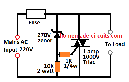
Parts List
- Resistor 1/4 watt 5% 1 k = 1
- Resistor 10 k 2 watt = 1
- Zener diode 270 V 1 watt = 1
- Fuse = 1
Here, the zener voltage decides the cut off limit of the crowbar circuit. In the figure it is shown as 270V, therefore as soon as the 270 V mark is reached, the zener starts conducting. As soon as the zener diode breaks over and conducts, the triac is switched ON.
The triac switches ON and short circuits the line voltage thereby bowing off the fuse the preventing further dangers that may resulted in due to the high voltage.
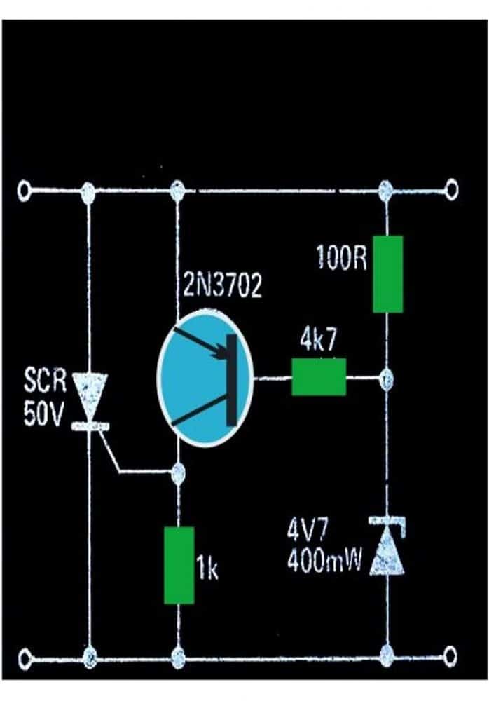
Another Simple SCR, Fuse Crowbar Circuit
This is yet another simple SCR transistor crowbar circuit which delivers over-voltage protection in case there is a malfunction of the voltage regulator or high level from an external source.
It is supposed to be employed with a supply source that includes some type of short circuit protection, possibly fold-back current limiting or a basic fuse.
The best possible application can be a 5V logic supply, because TTL could be quickly destroyed by too much voltage.
The values of the parts selected in Fig.1 are with respect to a 5V supply, even though any kind of supply up to about 25V could be protected using this crowbar network, just by picking the right zener diode.
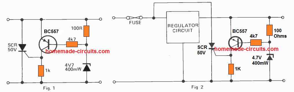
Any time the supply voltage is greater than the zener voltage by +0.7V, the transistor activates and triggers the SCR.
When this happens it short circuits the supply, stopping the voltage from increasing any more.
If it is used in a power supply which only has a fuse protection, it is advisable to attach the SCR right around the unregulated supply as indicated in Fig.2 in order to protect against damage to the regulator circuit as soon as the crowbar triggers ON.
SCR Specifications
The thyristor or the SCR must be rated with a current that may be approximately two times the anticipated short circuit current value and rated with a optimum voltage that must be higher than the input supply voltage.
For resetting the circuit in the original condition you can either switch off the supply source, or do it by interrupting the SCR conduction through a push button switch across its cathode/anode terminals.


Questions & Answers
Hi, i want to use the simple circuit crowbar to protect 220Vac line.
I built the circuit posted on your page. The fuse always blows as soon as I power the circuit. I tried removing the 270V zener, but the fuse still blows. I removed the triac, and, of course, the fuse no longer blows.
Hi, I am sorry about the problem you are facing,

Can you please replace your existing circuit with the following one, and please let me know how it works:
Hi,
Contrary to what I said previously, I retested the second suggested circuit. After replacing the two resistors (they were SMD) with two traditional resistors (through-hole), the fuse blew again.
Hi, please try the following design, I have simulated this circuit and it seems it is working. The fuse blows whenever the input voltage exceeds 290V peak. You can remove the bulb, it is not required…

Hi
I tested the circuit with the two zeners. On the third power cycle, the fuse didn’t blow; it literally exploded.
Hi, Now you think how can the triac conduct if it has two anti-series zener diodes on its gate?? There’s no way the triac can conduct unless the voltage exceeds 270V?? Maybe the gate resistor needs to be increased to 10k…
Hi,
i actually use a bta208s.
I think the problem is that, without pulldown, it always triggers.
I’m doing further testing and considering a different T435-800 triac. I’ll keep you updated on my progress.
Sure, no problem! please do keep us updated on the progress…thanks for the feedback!
Thanks for your reply.
With the circuit you suggested, under normal conditions (220 VAC), the fuse no longer blows. However, the two 10kΩ resistors are overheating (about 100°C). Furthermore, I haven’t yet tested whether the protection kicks in correctly at 270 VAC. I haven’t tried it yet because of the excessive heating of the two resistors, which I believe to be excessive.
if i use the simple crowbar circuit and replace the 10 amp fuse with a 25 amp because my radio draws about 20 amps, will the rest of the components stay the same. thank you bill
You will have a to use a 30 amp SCR and also dimension the zener diodes appropriately as per the voltage specifications of your radio.
thank you i figure a 15 volt zener should work?
Ok, no problem…
I have required the over voltage control fixed 220v out put . Not control under volt. only over voltage control fixed 220v
You can try this design:
Hello Swagatham,
Hope you are doing good.
I am looking for crow bar protection CKTs for my 48V batt Charger. I am using dual power supply [LM317 &337] for battery charging purpose, the charger o/p is tuned for 57V now. But I like to put a crow bar ckt at the o/p before the load and I want to limit the o/p to 60V max. Coz If there is an internal short in the LM317 or 337 the o/p will be maximum intern it may damage the battery pack.
So I am planning to use your “Crowbar circuit using Triac and Zener Diode” CKT. I am Selecting the 60v Zener and can you suggest the Triac for the following application?
I will use fast blow fuse according to the current rating of the ckt.
Thanks
Vijay
Thank you Vijay,
Yes you can try that circuit with a 60 V zener diode and a fast blow fuse. The triac can be a BT136 triac
Swagatham,
Thanks for the reply. I will get it. And is this ckt tested already with actual load?
Vijay
Actually I have not tested the circuit. I have created the circuit by studying the datasheet of the IC. According to my knowledge the design is correct and should work. With a load connected there might voltage spikes across the mosfets, which can be tackled by connected reverse diodes across the mosfets and by connecting a 100uF capacitor across the IC terminals along with a 12V zener diode across the supply terminals of the IC.
Thank you Swagatam for your good work. Please can I use 270V MOV (varistor) in place of zener diode in the 3rd circuit. The maximum value I could find in the shops around me is 36V type and I don’t want to use many components. I will appreciate your quick response.
Thanks once again.
Hi Samson, you can try an MOV, however I think a zener would give better results. You can easily use around 8nos of 36V zener in series to create a 270 V zener. 8 zeners won’t occupy to much space.
Can normal diac replace SBS in the Ac crowbar circuit. I could not find SBS in my area
Diac will require higher voltage, upto 35V to fire, whereas the SBS would fire at around 8 V, so diac cannot be used.
Good day Sir, Swag, how will I do the regulator circuit in the last diagram?
Seun, Where do you intend to use it and for what purpose?
AC line, high voltage damages 0
Then you can use a second last circuit or the 3rd last circuit with a fuse.
Hi I need help I have a instrument which works with up to 60v DC either way round.i need to protect this 60v DC or higher and have circuit ressetable or fused pls.give me all drawing with all components labelled thks alot
With fuse it is already shown in the article….do you also want with a relay??
Regarding a crowbar for a negative supply…
Use the same circuit.
Just connect it the right way round across the supply.
Anode of the SCR to the positive and cathode to negative. The circuit does not care which is ‘ground’.
Hello. The principle of operation of the circuit would be the same as for positive voltage. Only with negative tension. It would have to be a circuit with TRIAC (I think, because the SCR doesn’t work with negative voltage. Right?).
In other words: Close short (and blow fuse) if the voltage exceeds the pre-established limit.
With this protection you will know before burning the components of the circuit that is powered if the problem is in the circuit itself or in the source that supplies it.
(for example in a symmetrical source where you have + VCC and -VCC.
+ VDC- Voltage 16v = OK. voltage 16.5v = Burn out fuse.
-VCC – voltage-16v = OK. voltage-16.5v = Burn out fuse.)
Independent protections.
This circuit is for + VCC.
And for -VCC? How to make?
I don’t know if I made myself understood …
Searching on Google I found nothing regarding the CROWBAR protection with negative voltage.
You could help me?
If possible with the formulas for calculating the stresses.
I thank you for your attention.
Sorry for the translation (Google)
Luiz Pavão
You mean to say crowbar for AC?
You can try the following design:
Olá . Gostaria de saber como fazer esse tipo de circuito para tensão negativa.
Obrigado.
Pavão
Hi, sorry I did not understand how the negative voltage crowbar would work?
Hi, I have a tiny wind generator ( a toy ) and would like to use it as the basis for a strong wind alarm..is it possible to modify the crowbar circuit to incorporate a buzzer?
It will generate about 5 v with enough output to light an LED in normal circumstances..I would like to connect to a modified version of the crowbar to a relay board that I have so that if the wind speed rises and the unit generates 6 v or more it can trigger the alarm relay circuit.
Regards
David B
Hi, you can connect the buzzer in series with the 4k7 resistor. If the transistor does not conduct satisfactorily, you may try reducing the 4k7 to 1k.
Input is 18v
try 18 V zener diode, and also replace 100 ohm with 1K
I want the set limit to be 15v, how will I select appropriate components value
What is the input volts and from where it is acquired?