Making a zero crossing detector circuit is actually very easy and it could be effectively applied for protecting sensitive electronic equipment against mains switch ON surges.
A zero crossing detector circuit is mainly used for protecting electronic devices from switch ON surges by ensuring that during power switch ON the mains phase always "enters' the circuit at its first zero crossing point.
Strangely, except "wikipedia" no other top online site has so far addressed this crucial application of a zero crossing detector concept, I hope they will update their articles after reading this post.
What is a zero crossing detector?
We all know that our mains AC phase is made up of alternating sinusoidal voltage phases as shown below:
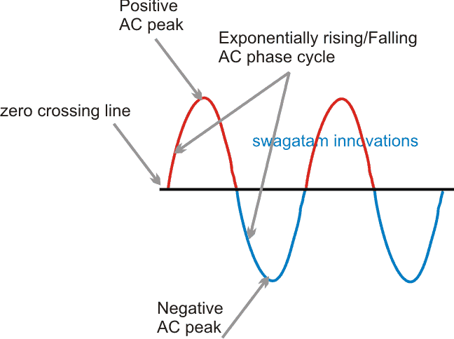
In this alternating AC, the current can be seen alternating across the central zero line and across the top positive and bottom negative peak levels, through a particular phase angle.
This phase angle can be seen rising and declining exponentially, meaning it is doing so in a gradually rising and gradually falling manner.
The alternating cycle in an AC happens 50 times per second for 220V mains and 60 times per second for 120V mains inputs as set by the standard rules. This 50 cycle response is called 50 Hz frequency and the 60 Hz is called 60 Hz frequency for these mains outlets in our homes.
Whenever we switch ON an appliance or an electronic device to the mains, it is subjected to a sudden entry of the AC phase, and if this entry point happens to be at the peak of the phase angle could imply maximum current being forced to the device at the switch ON point.
Although, most devices will be ready for this and might be equipped with protection stages using resistors, or NTC or MOV, it is never recommended to subject them to such sudden unpredictable situations.
To tackle such an issue, a zero crossing detector stage is used which ensures that whenever a gadget is switched ON with mains power, the zero crossing circuit waits until the AC phase cycle reaches the zero line, and at this point it switches ON the mains power to the gadget.
How to Design a Zero Crossing Detector
Designing a zero crossing detector is not difficult. We can make it using an opamp, as shown below, however using a opamp for a simple concept as this looks to be an overkill, so we'll also discuss how to implement the same using an ordinary transistor based design:
Opamp zero crossing detector circuit
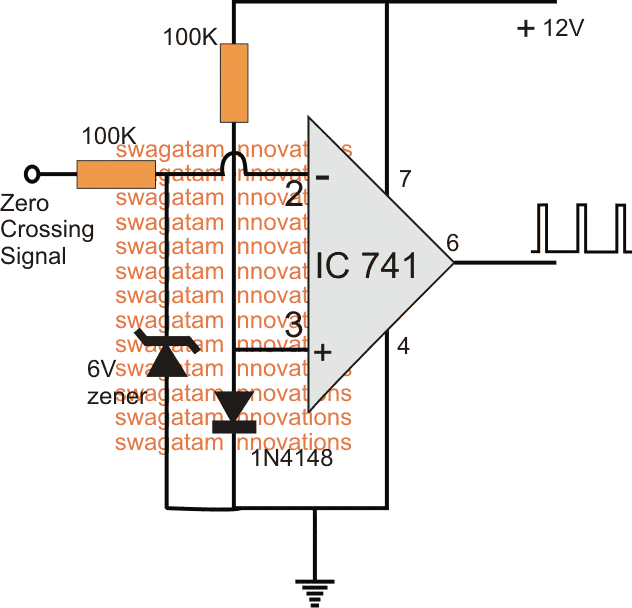
The figure above show s simple 741 opamp based zero crossing detector circuit which can be used for all applications requiring a zero crossing based execution.
As can be seen, the 741 is configure as a comparator, wherein its non-inverting pin is connected with ground through a 1N4148 diode, which causes a 0.6V drop potential at this input pin.
The other input pin#2 which is the inverting pin of ther iC is used for the zero crossing detection, and is applied with the preferred AC signal.
As we know that as long as pin#3 potential is lower than pin#2, the output potential at pin#6 will be 0V, and as soon as pin#3 voltage goes above the pin#2, the output voltage will quickly switch to the 12V (supply level).
Therefore within the fed input AC signal during the periods when the phase voltage is well above the zero line, or at least above the 0.6V over the zero line, the opamp output shows a zero potential....but during the periods when the phase is about to enter or cross the zero line, the pin#2 experiences a potential below 0.6V reference as set for pin#3, causing an immediate reversion of the output to 12V.
Thus the output during these points becomes 12v high level, and this sequence goes on triggering each time the phase crosses the zero line of its phase cycle.
The resultant waveform can be seen at the output of the IC which clearly expresses and confirms the zero crossing detection of the IC.
Using a opto-coupler BJT circuit
Although the above discussed opamp zero crossing detector is very efficient, the same can be implemented using an ordinary opto coupler BJT with reasonably good accuracy.
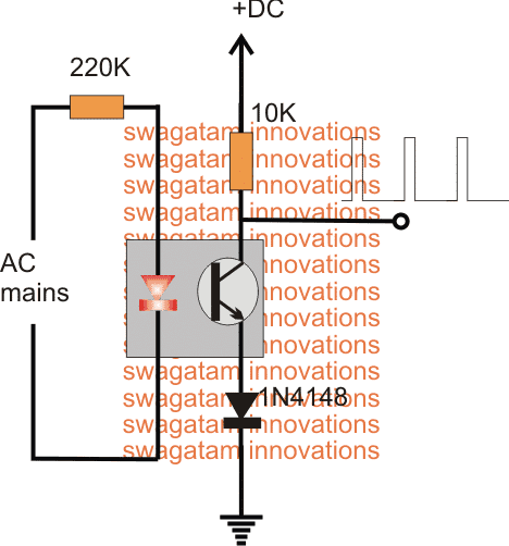
Referring to the image above, the BJT in the form of a phototransistor associated inside an opto coupler can be effectively configured as a simplest zero crossing detector circuit.
The AC mains is fed to the LED of the opamp via a high value resistor. During its phase cycles as long as the mains voltage is above 2V, the phototransistor stays in the conducting mode and the output response is held at near zero volts, however during times when the phase reaches the zero line of its travel, the LED inside the opto shuts off causing the transistor to also shut off, this response instantly causes a high logic to appear at the indicated output point of the configuration.
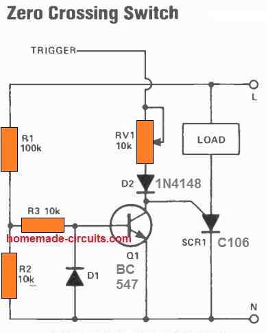
Practical Application circuit using zero crossing detection
A practical example circuit using a zero crossing detection can be witnessed below, here the triac is never allowed to be switched at any other phase point except the zero crossing point, whenever power is switched ON.
This makes sure that the circuit is always kept away from the switch ON current surge, and from its relevant dangers.
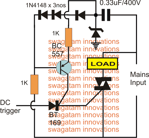
In the concept above, a triac is fired through a small signal SCR controlled by a PNP BJT. This PNP BJT is configured to execute a zero crossing sensing for the intended safe switching of the triac and the associated load.
Anytime when power is switched ON, the SCR gets its anode supply from the existing DC trigger source, however its gate voltage is switched ON only at the moment when the input transits through its first zero crossing point.
Once the SCR is triggered at the safe zero crossing point, it fires the triac and the connected load, and in turn becomes latched ensuring a continual gate current for the triac.
This kind of switching at the zero crossing points every time power is switched ON ensures a consistent safe switch-ON for the load eliminating all possible dangers that is normally associated with mains sudden power switch ON.
RF Noise Elimination
Another great application of a zero crossing detector circuit is for eliminating noise in triac switching circuits. Let's take the example of an electronic light dimmer circuit, we normally find such circuits emitting a lot of RF noise into the atmosphere and also into mains grid causing unnecessary dumping of harmonics.
This happens due to the rapid intersection of the triac conduction across the positive/negative cycles via the zero crossing line...especially around the zero crossing transition where the triac is subjected into a undefined voltage zone causing it to produce rapid current transients which in turn are emitted as RF noise.
A zero crossing detector if added to triac based circuits, eliminates this phenomenon by allowing the triac to fire only when the AC cycle has crossed the zero line perfectly, which ensures a clean switching of the triac, thererby eliminating the RF transients.
Using an Opto Coupler
A good zero crossing load circuit can be built using the following configuration.
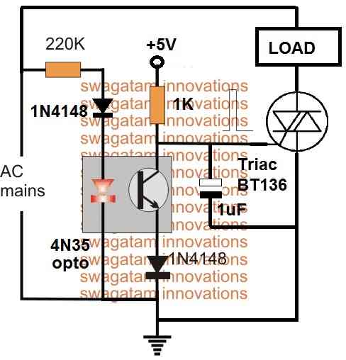
The circuit uses an opto coupler to switch ON an associated triac exactly when the AC phase passes through the zero crossing line.
As long as the phase cycle is above the zero crossing line, the opto coupler LED remains switched ON which in turn causes the opto transistor to remain switched ON. During this period the triac gate is held at the ground potential which keeps it switched OFF.
The moment the AC phase reaches the zero crossing line, the opto LED and the transistor are turned OFF, allowing the triac gate to get the required switching voltage from the +5V source.
The triac now switches ON and operates the load.
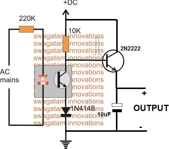
Opto Coupler with Transistor
The above explained opto coupler with zero crossing detector can be also modified with an external transistor for powering sensitive DC electronic circuits. The complete circuit diagram is shown in the following figure:
Reference:


Questions & Answers
buenas noches soy Freddy tecnico en electronica jubilado pero me mantengo activo para no herrumbrarme me encanta la electronica construlo moches proyectos con arduino y derivados mas por joby pero estoy tratando de hacer un proyecto diferente para mi es un estabilizador de frecuencia de 60hz 220v AC de un generador accionado por un motor la idea es que cuando la frecuencia suba o baje 3hz +- se activen 2 rele uno es para un ventilador y el otro es para un moc3041 y activar un triac de potencia pero lo que no me sale bien es el circuito creuce por cero yo lo quiero hacer en un arduino nano en el programa es en pin D2 pero no lo logro ativar lo e diceñado de varias formas pero nada seria de mucha ayuda un buen consejo gracia saludos
Thanks Freddy, here’s my suggestion:
You can use a PC817 optocoupler, then connect two 100k resistors in series on the mains side.
First we take the 220V AC line. From the LIVE wire connect one 100k 1 watt resistor. From its other end connect another 100k 1 watt resistor in series…
Then the free end of the second 100k resistor goes to pin 1 (anode) of PC817. Pin 2 (cathode) of PC817 goes directly to NEUTRAL of AC…
Now we move to the low voltage side, which is safe side.
Pin 3 (emitter) of PC817 goes to Arduino GND, and the Pin 4 (collector) goes to Arduino D2.
Then connect one 10k resistor between Arduino 5V and D2, which acts as pull-up, so when output releases then it rises properly.
When AC waveform moves away from zero then the internal LED of PC817 conducts, so D2 stays LOW. When waveform comes near zero then LED turns OFF, therefore D2 goes HIGH through the 10k pull-up. So you get narrow HIGH pulse at every zero crossing, simple behavior.
If mains is 60Hz then you get 120 pulses per second, since every cycle has two zero crossings, so count becomes double. If you use interrupt on D2 in RISING mode then you can measure frequency cleanly.
Hi Swagatam,
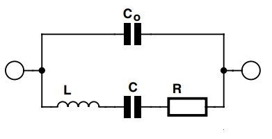
I agree with you on the circuitry — but the question I have is – do you know of a way to develop the AC voltage signal – without influencing an extremely high Q resonating tank circuit.
If you insert an in-line resistor – it will go flat.
If you interact magnetically — it will change the inductive reactance value and change the frequency – with the same result if the capacitive reactance value is changed.
“Getting” the AC signal is the problem.
ANy thoughts would be appreaciated.
Hi Scott,
In the last circuit if you replace the opto-coupler with an FET, then it can work like a high impedance buffer to accomplish the results.
The gate can be added with a 100k resistor, and a 12V zener diode across its gate and source to ensure a safe gate voltage.
Does it make sense?
Hi Swagatam,
I’m sending this question again – as I don’t know if it went through the first time.
I have an electrical situation where I need to detect the ZVC point in a 480 VAC / 50 kHz / resonating AC tank circuit — producing a positive only going / very small duty cycle / 12 VDC square wave output signal – in be in as close “in-phase” with the tank circuit.
Any ideas would be greatly appreciated.
Thanks in advance,
Hi Scott,
I think the last circuit from the above article can be customized for your application.
Please let me know if you have any further questions.
Will this circuit also ensure that the load switches off at zero crossing?
I have an air conditioner that frequently trips the GFCI plug only when the compressor turns off. There is never a problem on starting. I installed a fused power bar between the GFCI plug and the air conditioner and that fuse trips instead and protects the GFCI plug.
Can you please tell, which circuit are you referring to?
I meant; Will any (or all) of these circuits produce zero crossings shut off.
The circuits will switch ON or trigger ON the output during the zero crossing, so it will do the opposite.
I’m not clear on what opposite is. Will it turn off on zero crossings or will the circuit turn off at the random time the trigger is received?
Thank you for your speedy response to my questions. It is appreciated.
The outputs of all the circuits will remain switched ON during the zero crossing period of the input AC signal. The switch ON periods of the output will indicate the zero crossing periods of the input AC. The circuit outputs will turn OFF when the zero crossing voltage has exceeded around 1 V.
In the second circuit the current limiting resistor (220k in your case) should be wirewound type resistor or something else? Also how to calculate the wattage? Should we aim for lower or higher wattage?
A simple 1/4 watt CFR resistor will do.
Thank you.
Why is it so high resistance? At 230 volts you get 1,04 mA forward current. Is this enough for your optocoupler?
You can try 100k also, the 220k value was selected randomly because I guess even a slightest bit of illumination of the opto LED is enough to drive the transistor ON.
But I think in a real situation where you need for example 10 mA to turn on the LED in your optocoupler, you would only need 23 kOhm at 230 Volts. Am I way off? Is there something I’m not taking into consideration?
An LED will stat illuminating even with a 1 mA current although the illumination will be very dim, barely visible in dark. So the process of illumination is not sudden, rather it follows the intensity of the current from minimum to maximum.
Yes 23k would work but it would dissipate a lot of heat, therefore it will need to be a high watt resistor.
Your statement: As we know that as long as pin#3 potential is lower than pin#2, the output potential at pin#6 will be 0V, and as soon as pin#3 voltage goes above the pin#2, the output voltage will quickly switch to the 12V (supply level) is not quite correct. The voltage at pin 2 will fall below the reference voltage applied to pin 3.
My statement is correct, it is a basic comparator rule….. the input is supposed to be fed from a bridge rectifier
Hi swagatam,
I tried the second circuit with a bridge rectifier and mct2e. If I try 180k 0,25W resistor, temperature of the resistor seems to be ok.
But If y try 180k 1W resistor it’s very hot (can’t touch the resistor more than 3seconds.)
Is it normal?
If I put 43k 1W resistor before bridge rectifier on line and neutral they are hot too.
Hi Johann, It is normal, however I would rather suggest to add a 0.22uF/400V or 0.33uF/400V capacitor in series with the resistors and then reduce the resistor value to 10k (4.7k + 4.7k) 1/4 watt, and see the effect
hello dear sir,God bless you .i always read your site and through site i was able to be almost a few successful in electronics. both zero crossing detectors can not be effective in the negative cycle, My dear friends,i designed a very good circuit that is very effective ,accurate and simple ,and i use this circuit a lot to control triak device and i wanted to share this circuit with you,noble man
Thank you Dear Sedigh,, all the above circuits are supposed to be fed from a bridge rectifier, not from an AC source, and therefore both the cycles will be processed!
I have put a note below all the diagrams for clarifying the issue!
I would also question the description of the 3rd circuit as it would seem that the base of the PNP is 3 diodes lower than it’s emitter during positive half cycle, hence able to supply current to the SCR trigger device. So I do not see how it stops the circuit being triggered during a positive cycle. The diagram is missing a capacitor on the emitter of the PNP. Without this capacitor, the PNP cannot provide trigger current during negative half cycle… but again, although it would then clear turn on a zero crossing, I cannot see any reason why it would not turn on during a latter portion of the AC cycle either positive or negative…. I’d be happy to discuss it further with you though!
The total diode drop at the base of the PNP will be around 2V, which means as long as the input positive cycle is above 2V across base/emitter, the PNP cannot conduct. Adding a capacitor will mean the PNP keeps conducting permanently due to the holding charge of the capacitor and will make the main purpose useless. The ScR gate current is decided by the 0.33uF value and seems to be quite enough for a SCR triggering. 0.33uF will provide around 15 mA sufficient for the ScR gate.
Hi,
Interesting stuff, thanks.
Regarding your “Using a opto-coupler BJT circuit” however, surely it will only work as described during the positive half of the A/C cycle.
During the negative half cycle the LED will also be off and the transistor non conducting resulting in a different o/p wave form than shown. Addition of a bridge rectifier feeding the LED would be required to obtain the pulse at every zero crossing as shown in your sketch. No?
Cheers,
Brian H.
Uxbridge Ont Canada
Hellow Swagatam, I quite understand the first two zero crossing circuits, but sir, to my understanding, the third circuit ‘practical application circuit might not work, it will conduct at the peak of the line voltage because the base of the PNP BJT is always lower than it’s emitter, and hence is forward biased. Please Sir, if it is a lack of enough understanding on my part, kindly explain how how the zero detection could be accomplished by the PNP BJT.
Hi Afolabi, The base of the PNP is connected with the positive line of the circuit via a few diodes. During the mains peak voltages this line will be at full 12V DC which will keep the PNP switched OFF. The PNP will be able to conduct only during the periods when the peak drops below 1.5V, when the base of the PNP will be able to access the ground negative potential. I hope you got the point.
Let me know if you have any further doubts.
hello swagatamji, do i required this circuit for SCR firing circuit.
can you pleas help to control SKKT 57B16E SCR in back to back model to control AC voltage.
hello Rohit, sorry I do not have an SCR controlled dimmer circuit at the moment with me…