In this post I will show how to construct an Arduino based wireless thermometer which can monitor the room temperature and external ambient temperature. The data is transmitted and received via 433 MHz RF link.
Using 433MHz RF Module and DHT11 Sensor
The proposed project utilizes Arduino as brain and the heart as 433 MHz transmitter/receiver module.
The project is divided into two separate circuits, the one with 433 MHz receiver, LCD display and DHT11 sensor which will be placed inside the room and also measures the room temperature.
Another circuit has 433MHz transmitter, DHT11 sensor for measuring outside ambient temperature. Both the circuit has one arduino each.
The circuit placed inside the room will display the internal and external temperature readings on LCD.
Now let’s take a look at 433 MHz transmitter/receiver module.
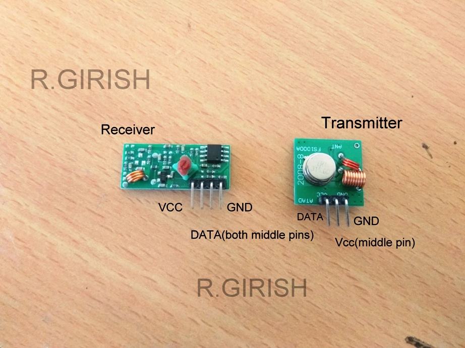
The transmitter and receiver modules are shown above; it is capable of simplex communication (one way). The receiver has 4 pins Vcc, GND and DATA pins. There are two DATA pins, they are same and we can output the data from either of two pins.
The transmitter is much simpler it has just Vcc, GND and DATA input pin. We have to connect an antenna to both modules which is described at the end of the article, without antenna communication between them won’t be established beyond few inches.
Now let’s see how these modules communicate.
Now assume we are applying clock pulse of 100Hz to the transmitter’s data input pin. The receiver will receive exact replica of the signal at receiver’s data pin.
That’s simple right? Yeah… but this module works on AM and susceptible to noise. From author’s observation if the transmitter’s data pin left without any signal for more than 250 milliseconds, the receiver data output pin produce random signals.
So, it is only suitable for non-critical data transmissions. However this project works very well with this module.
Now let’s move on to schematics.
RECEIVER:
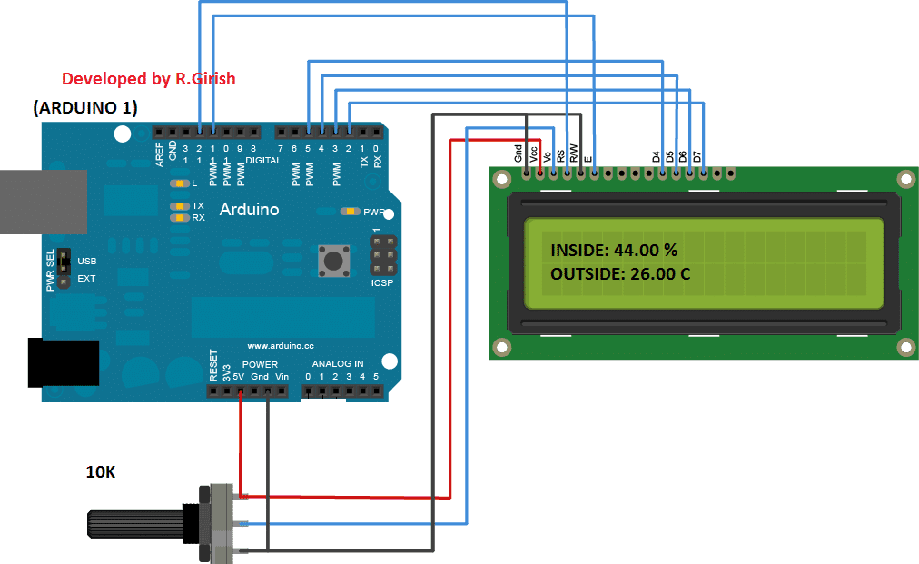
The above circuit is arduino to LCD display connection. 10K potentiometer is provided for adjusting contrast of LCD display.
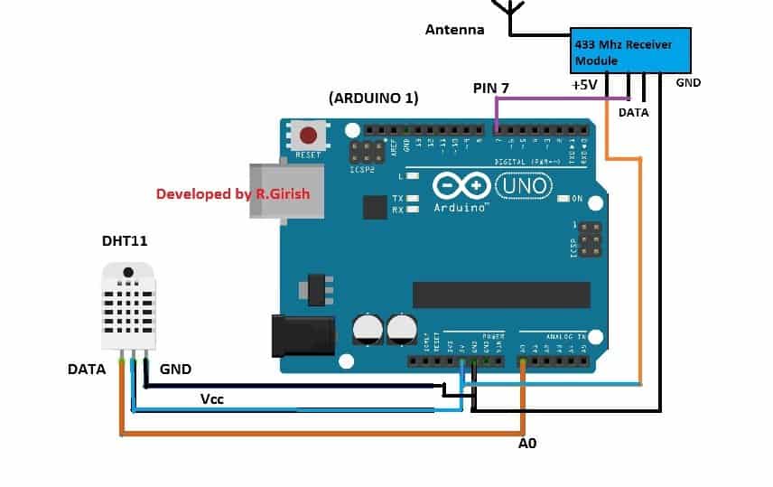
The above is the receiver circuit. The LCD display should be connected to this arduino.
Please download the following library files before compiling the code
Radio Head : github.com/PaulStoffregen/RadioHead
DHT sensor library : https://arduino-info.wikispaces.com/file/detail/DHT-lib.zip
Program for Receiver:
//--------Program Developed by R.Girish-----//

#include <LiquidCrystal.h>
#include <RH_ASK.h>
#include <SPI.h>
#include <dht.h>

#define DHTxxPIN A0

LiquidCrystal lcd(12, 11, 5, 4, 3, 2);
RH_ASK driver(2000, 7, 9, 10);

dht DHT;
int ack = 0;

void setup()
{
  Serial.begin(9600);
  lcd.begin(16, 2);
  lcd.clear();

  if (!driver.init())
  {
    Serial.println("init failed");
  }
}

void loop()
{
  ack = 0;

  int chk = DHT.read11(DHTxxPIN);

  switch (chk)
  {
    case DHTLIB_ERROR_CONNECT:
      ack = 1;
      lcd.setCursor(0, 0);
      lcd.print("INSIDE:        ");
      lcd.setCursor(0, 1);
      lcd.print("NO DATA        ");
      delay(1000);
      break;
  }

  if (ack == 0)
  {
    lcd.setCursor(0, 0);
    lcd.print("INSIDE:        ");
    lcd.setCursor(8, 0);
    lcd.print(DHT.temperature);
    lcd.print(" C");
    delay(2000);
  }

  uint8_t buf[RH_ASK_MAX_MESSAGE_LEN];
  uint8_t buflen = sizeof(buf);

  if (driver.recv(buf, &buflen))
  {
    String str = "";

    for (int i = 0; i < buflen; i++)
    {
      str += (char)buf[i];
    }

    lcd.setCursor(0, 1);
    lcd.print("OUTSIDE:       ");
    lcd.setCursor(8, 1);
    lcd.print(str);

    Serial.println(str);
    delay(2000);
  }
}

//--------Program Developed by R.Girish-----//
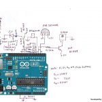
Transmitter:
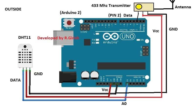
The above is the schematic for Transmitter, which is fairly simple as receiver. Here we are using another arduino board. The DHT11 sensor will sense outside ambient temperature and send back to receiver module.
The distance between transmitter and receiver should not be more than 10 meter. If there are any obstacles between them, transmission range may get reduce.
Program for Transmitter:
//------Program Developed by R.Girish----//

#include <RH_ASK.h>
#include <dht.h>
#include <SPI.h>

#define DHTxxPIN A0

int ack = 0;

RH_ASK driver(2000, 9, 2, 10);
dht DHT;

char tempMsg[10];

void setup()
{
  Serial.begin(9600);

  if (!driver.init())
  {
    Serial.println("init failed");
  }
}

void loop()
{
  ack = 0;

  int chk = DHT.read11(DHTxxPIN);

  switch (chk)
  {
    case DHTLIB_ERROR_CONNECT:
      ack = 1;
      driver.send((uint8_t *)"NO DATA", 7);
      driver.waitPacketSent();
      break;
  }

  if (ack == 0)
  {
    int t = DHT.temperature;

    if (t >= 15 && t <= 50)
    {
      sprintf(tempMsg, "%02d.00 C", t);
      driver.send((uint8_t *)tempMsg, strlen(tempMsg));
      driver.waitPacketSent();
    }

    delay(500);
  }
}

//------Program Developed by R.Girish----//
Construction of Antenna:
If you are building projects using this 433 MHz modules, follow the below constructional details strictly for good range.
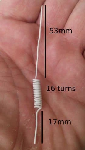
Use a single core wire which should be sturdy enough to support this structure. You can also use insulated copper wire with insulation removed at bottom for solder join. Make two of these, one for transmitter and another for receiver.
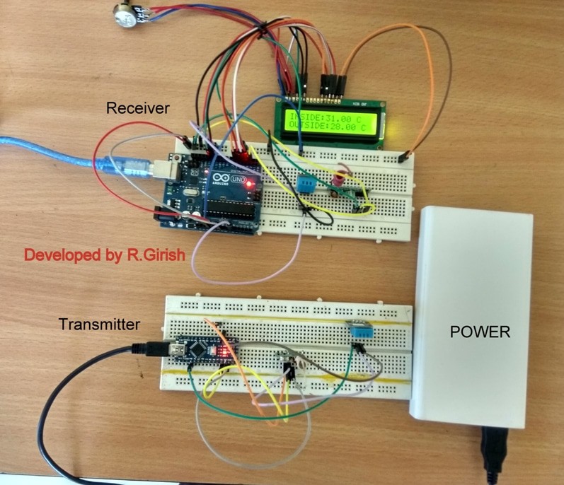
Author’s Wireless Thermometer Prototype using Arduino and 433 MHz RF Link:


Comments
I just tried the 2 meter wire and it works great and I just used 24 AWG solid core. I will try the larger stranded wire tomorrow. I am so happy to have this solution! Thanks so much!
that’s great Norman…keep up the good work..
Hi Swagatam! I have been working with 433mhz Rx/Tx circuits and have some questions. I have tried several systems with HT12e & HT 12d encoders/decoders. Some work and others don’t. So I decided to try ready made modules for RF remote controlled relays. Again, some work and others need to be within15mm to work. I changed the antennas to a 1/4 wave (173mm) and 1/2 wave (346mm) with some success. I could not get the full wave antenna to work. The best is a 1/4 wave on the transmitter and a 1/2 wave on the receiver. While working with these units, I have noticed that if I touch the antenna of the transmitter with my hand while sending, The distance range is doubled or even tripled. How can I duplicate this without touching the antenna? Am I adding capacitance with my body? Please explain, so I can get greater distance with these wireless modules. I want to trigger the transmitter with a transistor, so I will not be there to touch the antenna. Thanks!
Hi Norman, That looks strange…I have also worked with quite a few readymade RF 433MHz modules but I have never faced any such issues with them, I could easily get around 60 meters of range from each of them by suitably increasing the Tx/Rx antennas. Make sure that your units are from reputed and branded companies only.
According to me simple flexible wires work the best as antennae for these units. just connect the 2 meter long flexible wire with their existing coiled antenna ends, and see the difference, you may immediately witness an enhanced range.
I don’t think its the capacitance of the body, rather our body too acts like an elevated antenna having large radiating area which helps radiate the signals with a better efficiency.
Thanks! I will try it out. What AWG wire and should it be solid core wire? Should it be straight or coiled as their antenna wire is coiled? The wire I am using now is 24 AWG and is solid core and is straight.
Any ordinary flexible wire can be tried, for example a 14/36 wire, that’s 14 strands of 36 SWG wire. I prefer using a multi strand wire which works better, especially due to their flexibility which allows easy tweaking and optimization of their orientation.